7

I'm making a laser spirograph for a school project. It requires speed control of three motors. I used a simple 555 astable circuit with a pot for control, then the output goes into the base of a power transistor to make a PWM ground. I had indicator lights for all of them, and when the motors are off, I get a got a good pulse, but when I turn the motors on, they just stay at the same speed no matter what I do, and the indicators go dim (parallel to motors with a resistor). I think it might be because its just sucking the power from the transistor or something, but I can't be sure. Any help or Ideas? Schematic: Note: There are three of these modules in the circuit. Schematic

Transistor Package:Transistor

Kevin Macklin
  • 141
  • 1
  • 12
  • Can you post a schematic of your circuit? – Dave Tweed Jan 21 '13 at 22:31
  • You say there's a transistor, but the schematic doesn't show one. The motor does not have a current source other than the 555 timer. The 555 timer can only supply about 200mA of current, and I would presume the motor requires more. Is the schematic correct? – JYelton Jan 22 '13 at 01:09
  • Yep, I forgot to put that in. Ill post an update. – Kevin Macklin Jan 22 '13 at 02:31

2 Answers2

4

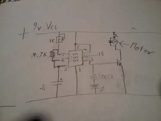
The indicators go off because your output is connected directly to the base of your power transistor, so it will be sinking a lot of current from the 555 output, and since the transistor base to emitter voltage is around 0.7V, it will cause the 555 output to sag too low to turn the LED on.

You need to put a resistor in series with the base of your transistor, to prevent it loading the output of the 555 too much and it's voltage dropping - I don't know what current your motor needs, or the gain of your transistor, but try 100Ω first. This will limit the current to (9V - 0.7V) / 100 = 83mA, which combined with the LED current is within the 200mA output spec of the 555, so it should easily be able to light the LED as well.

The 83mA will give you plenty of current at the base of your power transistor, so even if it's gain is very low, it only needs a gain of 25 to sink over 2A.
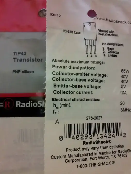
Transistor

Okay, we now have discovered that the schematic shows an NPN transistor but you are using a TIP42, which is a PNP transistor. A PNP is like an opposite version of an NPN, and to use it the voltages must be reversed in comparison. Look at the symbols for boht, note the difference in arrow direction - it always points to N type material (or away from P type)

NPN and PNP

You have a couple of options:

  • Use a TIP41 or similar NPN power transistor and use the current circuit with base resistor suggested.
  • Wire the circuit correctly to use your TIP42 PNP, which would look something like this:

555 PNP

Depending on how much current your motor is rated for, you may be better with a darlington or MOSFET, as the power transistors gain will drop at saturation, loading the 555 output too much so it may not have enough current to turn it on fully (which will cause it od disspate more power, etc) If it's under 1A you should be okay.

Oli Glaser
  • 54,990
  • 3
  • 76
  • 147
  • Thanks, that fixed the indicator, but the motor still isn't responding to the PWM. Do you think I need a faster switching transistor, if so, which one? – Kevin Macklin Jan 22 '13 at 05:25
  • Hard to say without a bit more info - what transistor are you using and what rating is your motor? If I understand correctly, the motor is working but just not changing speed when you turn the pot correct? – Oli Glaser Jan 22 '13 at 05:55
  • Maybe the transistors are broken. Vcc in base, gnd in emitter... That's not good for a bjt, even a power one. – Vladimir Cravero Jan 22 '13 at 07:17
  • If you are probing directly between the base and ground (i.e. after the series resistor you put in) and reading 9V then it's not good, no - it should be around 0.7V, unless it's a darlington, in which case it will be a bit higher (~1.5V). With the emitter though, it is connected to ground so it should be at 0V (the emitter is the side with the arrow pointing "south-east") Try another if you suspect it's faulty. What is the part number? – Oli Glaser Jan 22 '13 at 07:47
  • I added a picture of the transistor package. I bought 4 new from RS and I used one in a different project(LED Strobe) in the same way and it worked, but that was not with any motors. – Kevin Macklin Jan 22 '13 at 21:23
1

Oli's points are all good. Also, the transistor you are using, TIP42, is a PNP transistor. You have drawn your schematic with an NPN transistor. You can still make it work; start by putting the emitter to Vcc instead of GND, and add a base resistor as Oli suggested. The logic will be inverted; the motor will be on when the 555's output is low.

Phil Frost
  • 56,804
  • 17
  • 141
  • 262
  • Watched a simple video on transistors.(http://www.youtube.com/watch?v=F-Cv7CMHoGM) So what I need to do is switch the collector and emitter? – Kevin Macklin Jan 23 '13 at 01:39
  • @KevinMacklin yes, more or less. I just happened to draw [another 555 circuit with a PNP transistor](http://electronics.stackexchange.com/questions/55823/how-can-i-most-efficiently-drive-an-led/55824#55824). Just imagine your motor in place of L1. – Phil Frost Jan 23 '13 at 02:21
  • Wow, that's almost exactly the same circuit. – Kevin Macklin Jan 23 '13 at 03:30