0

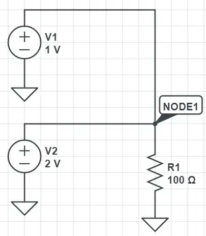
I am still having trouble understanding how voltage sources combine when they are connected in parallel. Consider the following circuit below:

enter image description here

If we assume that the wires connecting the resistor to the two voltage sources are perfect (zero resistance), then we get what appears to be a paradox since the voltage at node 1 needs to be both 1V and 2V at the same time. In reality, this situation is resolved by the finite resistance that real wires possess.

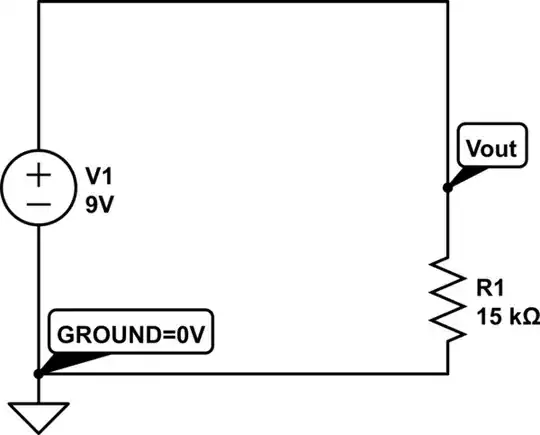
My misunderstandings occur when one of the voltage sources is an AC source such as below. In this case, is the voltage at node 1 really just a sum of the AC and DC sources? In this scenario, does this mean that the DC source outputs an AC current in order to maintain a constant voltage? Would this AC current coming from the DC source be in-phase with the current from the AC source in order to cancel out the AC source's effects on the DC source?

Also, for real world applications, does this type of connection lead to any negative effects that would damage the AC or DC source? I've seen suggestions that using a capacitor or transformer would be better to add AC and DC voltages rather than connecting them directly.
enter image description here

  • 1
    Well, like you said, you can't connect two voltage sources in parallel as it leads to a paradox, it does not matter if they are AC or DC sources. Connecting them in real world may damage them, but it depends which kind of voltage sources they are. – Justme Mar 28 '21 at 07:55
  • Yes but the situation is resolved if you consider the finite resistances of the wires. My misunderstandings occur when one of the sources is AC and the other is DC. – poopandstuff Mar 28 '21 at 07:56
  • Well if the voltage sources are ideal, and your wires have a finite resistance, then a finite but large current flows in the wire, and one end of wire is at one voltage and another end of the wire at another voltage. Current may be so large that the wire vaporizes. You can think of AC voltage source as time dependend DC voltage. – Justme Mar 28 '21 at 08:14
  • 1
    If you assume that the wires have finite resistance then the sources are **no longer in parallel**. Just add the resistance as an element in the schematic and solve the circuit. – Elliot Alderson Mar 28 '21 at 12:18

3 Answers3

2

Forget it. It's a short circuit. The current between the sources will become as high as the internal resistances of the sources and the wire resistance allow. In pure theory with ideal parts the current would be the voltage difference divided by zero Ohms, which we call infinite.

The problem vanishes if you have 2 resistors. Insert one resistor in series with each voltage source. Then you can connect them together for ex. to make a mixer for 2 signals.

Not asked: 1) Connecting AC and DC voltage sources in series is a common way to present a signal which has DC-component - a nonzero average. 2) Connecting in parallel current sources has no theoretical problems, but connecting 2 different current sources in series contains the same math impossibility than connecting 2 different voltage sources in parallel.

  • If we assume that the wires have finite resistance, say 10 Ohms, does this mean that the current outputted by the DC source is an AC current in order to maintain a constant voltage? – poopandstuff Mar 28 '21 at 08:09
  • I guess the resistances of practical wires is milliohms. That will be a short circuit for any 2V source a hobbyist can build. Insert at least hundreds of ohms or few kilo-ohms resistors. Learn circuit analysis to be able to calculate the result or use a circuit simulator. –  Mar 28 '21 at 08:17
  • Yes but in theory, would the current coming out the DC source be an AC current? My understanding is that the DC source will try to adjust its current such that its output voltage is constant. Working through nodal analysis seems to suggest this is true but I'm not confident with my answer. – poopandstuff Mar 28 '21 at 08:23
  • Yes, an ideal DC source can sink or source infinite amps to keep voltage at the set level. An ideal AC source can also sink or source infinite amps to keep voltage at set level. Infinite, or rather any current flows all the time. If there is a resistance of the wire, feel free to add that 0.001 ohms of wire resistance to your calculations to not go to infinities and be calculatable, in which case, the current will depend on the instantaneous voltage of the AC source. – Justme Mar 28 '21 at 08:34
  • Many practical sources such as voltage regulators based on transistor circuits do not allow current in both directions. A lead acid battery can as well be charged and discharged. –  Mar 28 '21 at 08:35
  • I see. Does this mean that if the voltage sources were bench power supplies, then the voltage source with the higher voltage would "win" and no current would be sourced from the lower voltage source? – poopandstuff Mar 28 '21 at 16:39
  • Many laboratory power supplies are designed so that connecting 2 of them in parallel doesn't puff the smoke out. Nothing else cannot stay alive for ex. in schools. If two of them are connected in parallel + output to + output an -output to -output the higher voltage very likely wins and the other does nothing but exists. If minus is connected to + and + to minus there probably are reverse protection diodes which short both outputs and the overcurrent protection limits the current or shuts the devices. –  Mar 28 '21 at 17:16
0

When you put in parallel 2 voltage sources you face 2 problems:

  1. Math

The system of linear equations will not lead to a unique solution unless the voltage sources have an internal resistance greater than zero.

  1. Lab

V1, V2 and V3 have an internal resistance greater than zero. Maybe less than 1 Ohm, but still greater than zero.

Wire's resistance must be accounted as well.

The voltage of Node 1 is obtained using the superposition of V1 and V2 and the solution is unique.

To answer your question:

I've never seen in 25 years of circuits design those kind of connections.

It's more common putting in series 2 or more voltage DC sources because maybe you need to generate a voltage greater than your instrument may do.

Enrico Migliore
  • 4,161
  • 1
  • 9
  • 12
0

I am still having trouble understanding how voltage sources combine when they are connected in parallel.

Without resistors to drop the voltage difference, theoretically infinite current would flow so, don't worry about it; nobody would do this without some form of voltage "blending" circuit (such as a resistor).

My misunderstandings occur when one of the voltage sources is an AC source such as below. In this case, is the voltage at node 1 really just a sum of the AC and DC sources?

No, it's not the sum but the average of both voltages (assuming both resistors have the same value).

In this scenario, does this mean that the DC source outputs an AC current in order to maintain a constant voltage?

The DC source is a source of constant voltage and will take or deliver current as demanded by the loading conditions (whether another source is present or not). In this scenario an AC current will flow as well as a DC current.

Would this AC current coming from the DC source be in-phase with the current from the AC source in order to cancel out the AC source's effects on the DC source?

The AC current from the AC source will be in phase with the AC current into/out of the DC source. "Cancellation" is not a thing here. Both supplies, when connected by resistors do exactly what is "says on the tin" - voltage sources are only interested in putting out the voltage that they are meant to produce. Whatever current flows as a result is of interest but, the motivation is not an attempt at cancellation.

Also, for real world applications, does this type of connection lead to any negative effects that would damage the AC or DC source?

"Damage" is strong word but it can happen especially with a voltage regulator circuit and, with transformers, you tend to not want too much DC current to flow.

Andy aka
  • 434,556
  • 28
  • 351
  • 777