-1

Why doesn't my IGBT module work? I shared my Multisim file as a download google drive file. Can you solve the IGBT problem? IGBT strangely doesn't work.

The emitter voltage is only 12V. I expected it to be equal to Vcc - about 98V.

enter image description here

enter image description here

enter image description here

IGBT test circuit schematic diagram Multisim file download.

JRE
  • 67,678
  • 8
  • 104
  • 179
  • 2
    Hi, Murat. I notice that you haven't "accepted" answers to any of your previous question. If you're not getting good answers it may be an indication that your questions need improvement. Accepting an answer is a way of thanking the contributors and marking the question as solved or answered satisfactorily. You can also upvote useful answers. – Transistor Mar 27 '21 at 15:06
  • I accept the answers. Whichever electronic scheme I worked with, I shared all of them with their photographs. To the one who will solve this job, I would like to thank you in advance as you said. igbt is really the problem. That's why there may not be many replies. – Murat Özen Mar 27 '21 at 15:10
  • 1
    No, there's a "check" √ button below the upvote / downvote buttons on each answer. You click that to indicate that the question has been answered. – Transistor Mar 27 '21 at 15:18
  • yes now I get it. Ok I will do this. I hope someone will come out who can solve the igbt problem. – Murat Özen Mar 27 '21 at 15:24
  • Is there a difference between the two schematics you posted? They are difficult to read. You have many unnecessary kinks and turns in the wiring. Q5 is upside down. You have ground symbols pointing sideways. If you clean it up you may see the problem yourself but it will help others also. You should crop the photos as > 50% is not relevant. You might find [rules-and-guidelines-for-drawing-good-schematics](https://electronics.stackexchange.com/questions/28251/rules-and-guidelines-for-drawing-good-schematics) a good help. – Transistor Mar 27 '21 at 15:29
  • I would question the simulation--I've never once seen an accurate SPICE model of an IGBT. – Hearth Mar 27 '21 at 15:33
  • First and second same picture but First Have 35 volt second is 100 volt results for showing to you – Murat Özen Mar 27 '21 at 15:35
  • Can you understand what is wrong with this circuit? I installed the irfp5210 p channel mosfet to switch the igbt. The irfp250n mosfet is controlling the irfp5210 p channeled MOSFET. Finally, the arduino uno development card irfp250n controls the MOSFET with 5 volts. But at high voltage igbt explodes – Murat Özen Mar 27 '21 at 15:42
  • that schematic is pretty horrible ... it is a visual equivent to fingernails on a chalkboard ... please orient R1, R2 and R4 vertically with GND on bottom ... flip Q5 vertically ... use a separate GND for each component ... remove random kinks in net lines – jsotola Mar 27 '21 at 17:40
  • 2
    Maybe your gate driver gets the gate up to 87V before your emitter can follow, causing Vge to exceed 20V in the transient case. I would put a 12V zener right across the gate and emitter to prevent this. – John D Mar 27 '21 at 17:45
  • 1
    @MuratÖzen: A clear, well drawn diagram doesn't make the circuit work any better. A clear, well drawn diagram makes it easier to read and understand your circuit. The better people can read and understand your circuit, the more inclined they are to help you figure out the problem. – JRE Mar 27 '21 at 23:38
  • 2
    @MuratÖzen: Your latest edit removed all the information about how the IGBT burns out and what voltages were present. Is the problem that the circuit doesn't deliver enough current, or is the problem that the IGBT burns out? – JRE Mar 27 '21 at 23:41
  • There was nobody who knew the subject and I solved the problem myself by doing trials while waiting for an answer. But then the voltage did not rise above 12 volts at all. I updated the experiment results. The subject is the same. I'm trying to drive igbt. How can I simplify the scheme. Driving iGBT with a p channel mosfet. It does this by connecting iGBT's positive pole to igbt's gate leg. The other irfp250 n-channel MOSFET turns on and off the p-channel MOSFET by means of the signals it receives from the Arduino. – Murat Özen Mar 28 '21 at 09:12
  • Okay I added Multisim File Download Link For Circuit Please Run and See this igbt is so strange. Even though I'm running full power, it can still send 12.4 volts at most. – Murat Özen Mar 28 '21 at 09:18
  • 2
    "*Please is there anyone on this forum site who understands electronics?*" Yes, very many. "*I can't find any answers. What does it have to do with the electronic circuit looking good and working cool?*" It's not about being cool, it's about being clear. If you won't bother to make it easy for your readers then you can't expect a quick response. You have been advised several times to do this so it appears that you do not respect your readers and are not really serious about seeking an answer. It should take you only a few minutes to fix. – Transistor Mar 28 '21 at 10:23
  • Okay sorry I fixed it – Murat Özen Mar 28 '21 at 10:54
  • 1
    @MuratÖzen: Not everyone has Multisim. Leave the circuit diagram pictures in the question. – JRE Mar 28 '21 at 11:18
  • OK . But really the situation is confusing. When I deactivate the trigger mosfet and manually power the gate leg, igbt only sends 12.4 volts of electricity. I saw it in real test . – Murat Özen Mar 28 '21 at 11:25

1 Answers1

0

Since you seem to have fixed the "burning" problem and now only have a "low output voltage" problem, I think I can help.

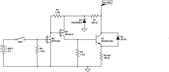
Your IGBT is being used in a way similar an emitter follower would be used with regular NPN bipolar junction transistor (BJT.)

With an NPN BJT emitter follower, the emitter will always be about 0.7 volts lower than the base voltage - regardless of the collector voltage.

It is similar with your IGBT. The emitter will always be a few volts below the gate. According to the IRG4PC30U datasheet, \$V_{GE}\$ is something between 3 and 6 volts.

You have D3 (1N5333B datasheet) there, clamping the gate to no more than 18V. That matches just your emitter voltage of 12V. 18 on the gate minus 6V \$V_{GE}\$ is 12V.

You are trying to use your IGBT as a high side switch. It would work better as a low side switch.

I've redrawn your circuit to be easier to read, and also so that I can modify it into a low side switch. The schematic editor on the site here doesn't have an IGBT symbol, so I used an NPN transistor but gave it the correct part number.

schematic

simulate this circuit – Schematic created using CircuitLab

With it drawn that way, it is clearly a high side switch. The voltage to the load can never be more than the voltage on the gate of the IGBT.

Here's your circuit redrawn as a low side switch:

schematic

simulate this circuit

Operated that way, you should get nearly the entire Vcc across your load.

I don't know enough about IGBTs to know if those resistors are anywhere near resonable.

Depending on the IGBT \$V_{GE}\$, you might be able to remove M1 and M2 (and the associated resistors) and just use the 5V directly - or maybe not. If you are using a microcontroller output rather than a battery then it won't be able to deliver the current needed to switch the IGBT quickly.

JRE
  • 67,678
  • 8
  • 104
  • 179
  • How do I boost the voltage it sends? I will run a 3 phase motor. I can run 3 negative pole phases with irfp250. I need 3 positive pole phases. If I run it with 12 volts, 3 negative phases and 3 positive phases turn the motor. It can do this with the Arduino uno control signal. But it should be able to send me exactly 100 volts and one ampere of positive electricity. Because I can only stop the three phaze motor with my finger. It is running only 12 volt. Not 0.7 volts I give 98 volts of electricity igbt only sends 12.4 volts. How can I fix this by making a change in the circuit? – Murat Özen Mar 28 '21 at 11:47
  • 1
    @MuratÖzen: Thank you for keeping such important details to yourself. You'll have to wait for somebody with more than a hobbyists understanding of electronics (that's me, hobbyist) for an explanation of how to design a how side switch with an IGBT. Switching speed is important, as well as the driving voltage for the gate. Getting both together is difficult enough that there are special IGBT gate driver ICs for high side switching. I know I don't know enough to design one that will switch fast enough to be efficient and not burn things out. – JRE Mar 28 '21 at 12:11
  • Hey my friend. I understand you and start to feel sorry for the situation. Because it's really hard not to know something and to say I don't know. Before I asked you this, I experimented with all the frequencies. I also experimented with the bulb before I asked this question. This means the following. This igbt circuit does not even run a simple light bulb. I know the switching speed is important. It cannot operate a simple light bulb either. – Murat Özen Mar 28 '21 at 12:37
  • 1. Put relevant details in your questions. 2. Include clear, understandable diagrams. 3. Also explain the ultimate goal of the circuit. 4. Don't change the question after people have begun commenting on it or have already answered it. 5. Don't insult people when they don't answer fast enough to suit you. 6. Well asked questions get answers faster than poorly written, unclear questions. – JRE Mar 28 '21 at 12:42
  • 1
    It can't operate a simple light bulb because you are incorrectly driving a high side switch. You have to have a high voltage on the gate to get a high voltage on the emitter. Your circuit can't do that. It can easily be a low side switch, but that apparently isn't sufficient. – JRE Mar 28 '21 at 12:46
  • Thank God I was finally able to find an answer. This is very good. So what circuit can do this? Is there a ready-made electronic scheme that you know will be able to do this for igbt module? As an example, google electronic circuit diagrams? – Murat Özen Mar 28 '21 at 13:03
  • 1
    [Take your pick.](https://www.infineon.com/cms/de/product/power/gate-driver-ics/high-side-drivers/) Use a proper driver. Look for "IGBT high side driver." – JRE Mar 28 '21 at 13:09
  • There is no technique on this site. They say they run it with a module on this site. OK . I will try to buy and run this module. I hope that when I apply this scheme exactly, this ready module will be able to run the igbt properly. – Murat Özen Mar 28 '21 at 13:12
  • Do you realize that your words come across as an insult? I'm not an engineer. I fiddle with electronics as a hobby. Your difficulties indicate that your skill level is lower than mine. Your initial (very unfriendly) question and your reaction to requests for a better schematic drove off most of the engineers who could answer your question. That you haven't accepted any of the answers to your previous questions also doesn't leave a good impression. – JRE Mar 28 '21 at 13:17
  • I'm spending my free time on a Sunday afternoon trying to explain this to you so that you can learn to participate better on this site, and so that you can learn to be better at the things you are working on. – JRE Mar 28 '21 at 13:18