10

enter image description here

Product Link

Datasheet

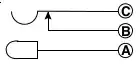
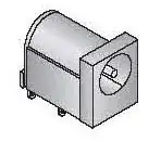
I have about fifteen 9v wall warts within specs for the circuit; I'm going to use the one that fits the jack. There are three solder tabs on the jack. One for the positive tip, one for the negative ring/sleeve, and one for the chassis ground. My schematic has Vin and ground specified. I'm relying on the wall wart to appropriately ground the AC end of things. My pos/neg tabs are used for source voltage and ground, respectively, and that leave the third chassis ground tab.

Do I ignore it? Connect it to the negative side ground? To the chassis? What should I do when there's no specification about what to do with the extra tab?

Dave Tweed
  • 168,369
  • 17
  • 228
  • 393
dwwilson66
  • 3,402
  • 11
  • 33
  • 42

3 Answers3

13

I don't think you are correct about a "chassis ground".

Every barrel-connector jack like the image you provide has three pins - Tip, sleeve, and connector-present.

Basically, there is an internal switch that is opened by the presence of a plug in the connector. It's often used to disconnect internal batteries when the device is powered off of an external supply.


Short of a few rather unusual laptop power supplies, every barrel connector I have ever dealt with has been two-conductor only.

Connor Wolf
  • 31,938
  • 6
  • 77
  • 137
  • 1
    +1 I hadn't realized the third pin was a connector-present indicator, that makes a lot of sense. – vicatcu Jan 21 '13 at 18:35
8

Fake Name's answer is correct, but I want to add an image from the datasheet:

schematic

There is no "chassis ground" anywhere in that datasheet.

Phil Frost
  • 56,804
  • 17
  • 141
  • 262
  • 1
    Glad to clear that up...I'd been misinformed. SO if I understand, this symbol indicates a switch between, say battery and wall power? I assume that woul dbe similar to an audio jack that silences the speakers when you plug in headphones? I'm having a major a-ha moment here. :) – dwwilson66 Jan 21 '13 at 19:02
  • 1
    @dwwilson66 yes, exactly. The schematic corresponds somewhat to the physical layout. That "U" on the top left contacts the barrel, and when you shove the plug in (from the left), this lifts up and no longer contacts _B_. – Phil Frost Jan 21 '13 at 19:12
1

Take a continuity meter to the two 'normally connected' pins out of circuit and I'm pretty sure notice that they ring out... I would say connect them together in your circuit - I have certainly done this in a couple designs (with a center positive jacks).

vicatcu
  • 22,499
  • 13
  • 79
  • 155