I've go a small scale strobe light and from the output I'm using a power transistor to amplify it and Then I have two sets in series of 5 LEDs in parallel with one 200 ohm resistor after the transistor (9v Vcc). The problem is that is I use it with one LED its very bright, but when I use the Dual 5LED parallels the LEDs are very dim and I need them to be as bright as possible. Probably very simple, but I could use some help with how to go about it.
Asked
Active
Viewed 835 times
3
-
2Can you show us a schematic diagram of your present setup? – Dave Tweed Jan 21 '13 at 00:01
-
1Related question: [Why exactly can't a single resistor be used for many parallel LEDs?](http://electronics.stackexchange.com/questions/22291/why-exactly-cant-a-single-resistor-be-used-for-many-parallel-leds) – Phil Frost Jan 21 '13 at 03:29
-
1Please add a schematic as requested by @DaveTweed – Chetan Bhargava Jan 22 '13 at 05:30
2 Answers
4
You will have a difficult time lighting LEDs in parallel reliably. A diode's relationship between current and voltage is subject to manufacturing variation and temperature dependence. When you put LEDs in parallel, the voltage across each must be equal, but the current may not be, because of these variations.
Importantly, a hot LED will draw more current at the same voltage than when its cold, so any LED which begins to heat unevenly will draw more current away from its parallel siblings, making it hotter, thus drawing more current. This sort of positive thermal feedback is called thermal runaway and is one reason why paralleled LEDs are avoided in all but the cheapest of cheap chineese flashlights.
That said, if all your LEDs are dim, it's likely because they are broken or not supplied with sufficient current. It sounds like you tried one LED with a resistor, and it was, then added more LEDs in parallel with the same resistor, and it was dimmer. If we just assume those LEDs share the current equally (ignoring the instabilities just mentioned), then they must share the current available. So, if you have 5 LEDs in parallel, each will have one fifth the current as there would be with just one LED.
Here's a simplified example, with just two LEDs in parallel, compared to just one LED:
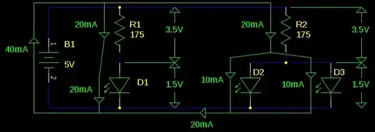
Here we assume that the voltage across an LED is always 1.5V. We know the battery is 5V, so the voltage across the resistors must be 3.5V. By Ohm's law, the current through R1 or R2 must be \$ 3.5V / 175\Omega = 20mA \$. On the left, this current has only one place to go, through D1. But on the right, this current is split in half.
Again, don't parallel LEDs like this. The problem is that between manufacturing variation and temperature dependence, we can't know if the LEDs will split the current 50%/50% or 10%/90%. If you size your resistor to supply enough current for five LEDs, and one ends up hogging all of it, it will probably get too hot and fail.
Phil Frost
- 56,804
- 17
- 141
- 262
-
-
@KevinMacklin think of what happens when a river forks. Electricity is no different. See illustration. – Phil Frost Jan 21 '13 at 03:16
2
With LEDs, you need a resistor for each one, as they do not share current equally if paralleled. You will need to calculate the resistor based on the Vf of the LED and it's maximum current rating. To increase the brightness, you need to reduce the resistance (increase the current for each LED, but remain below it's maximum)
Let's say your LEDs are typical red LEDs with a 20mA maximum rating. Red LEDs have a typical Vf of around 2V. Then your calculations are:
(Vsupply - Vf) / desired_current = resistor_value
So if we want the maximum 20mA, and we have a 9V supply, we get:
(9V - 2V) / 20mA = 350Ω
This means a separate resistor in series for each one.
If you tell us more about the LEDs (model number) and transistor then we can calculate specifically for your setup.
Just to explain about your current setup, the resistor will limit the current to a certain value (e.g. with the 7V across it as in the above example, 200Ω would be 35mA)
With one LED, it gets all the 35mA. With 5 LEDs, they get roughly 35mA/5 = 7mA each (in an ideal case, but since LEDs in parallel do not share the current equally unless it is controlled properly, the current each LED draws will vary considerably - you can read about it on the Wiki LED page.
Note the very sharp I-V curve, this is the reason the current must be controlled, the Vf drops as they get hotter, so they will draw more current, and get hotter, and the Vf drops, and... ...you get to the page on Thermal Runaway (in this case it would could also be referred to as current hogging - here is another good Wiki page on an LED circuit, explaining the reasons they must be current controlled).
All you can be sure of is that they will be dimmer since they only have the same current to share between 5 that the single LED had available)
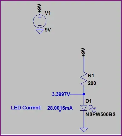
Okay, here is a demonstration with schematics:
One LED with a 200Ω resistor (current marked in blue - ~28mA):
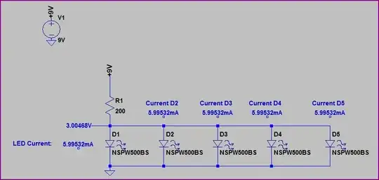
Now if we add the other 4 LEDs, but only use one resistor - note the current values have dropped (in the real world they would not be the same for each LED as mentioned above):
Now if we use a resistor for each LED, the current for each is the same as it was for the single LED:
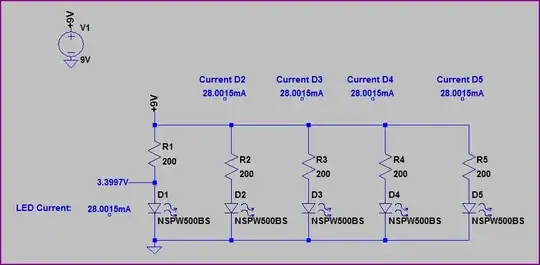
Hopefully, you can see why we need a resistor for each LED.
Oli Glaser
- 54,990
- 3
- 76
- 147
-
They are all white LEDs That were made for 200 ohms at 9v I think. If I had a resistor on each one, would it work in parallel? And why would you need one for each one in series, it seems like that would be too much resistance. – Kevin Macklin Jan 21 '13 at 00:49
-
Resistors in parallel add up to less resistance, it will work, yes - trust me ;-) For example, 2 x 100 ohm resistors in parallel would be 50 ohms (try it with a multimeter if you want to see for yourself) You need one on each because otherwise they will not share the current equally, and if too much current is available, will end up burning out. I will add a schematic - if they are white LEDs, then the Vf is higher (~3.5V), so they are probably set for about 20mA with the 200 ohms. – Oli Glaser Jan 21 '13 at 02:32
-
Okay, I added some schematics with the currents marked (ths is LTspice - a circuit simulator, which was used to calculate the currents) Looks like they are probably 30mA LEDs – Oli Glaser Jan 21 '13 at 02:56