0

Background: A robot uses two encoders attached to each rear wheel for feedback of speed. The program reading the encoders reads pulses per time unit. The encoders are sufficiently linear. The actuators are two DC motors attached to each rear wheel. They are controlled with PWM signals. So the controlled output signal is speed.

Problem: A PID controller is used to ensure that the robot wheels turn at the same speed so the robot can follow a straight course. The problem is that the program reads pulses/s while the output from the controller must be a PWM signal (a duty cycle value between 0-100). The system also faces different loads (varying surface friction and incline).

Questions

  1. How do I convert between the two units (i.e. pulses/s vs PWM) in the program?
  2. Even if I find a linear relation between input signal and output signal, doesn't this only hold true for a certain load (i.e. a certain surface friction and incline)?
  3. If the answer above is yes, then what purpose does a PID controller even have in this system?
Abdel Aleem
  • 111
  • 5
  • What your PWM is controlling? Is it the voltage? – Eugene Sh. Mar 22 '21 at 19:46
  • @EugeneSh. affirmative – Abdel Aleem Mar 22 '21 at 19:48
  • Why do you need to convert these units? Your PID controller has an input in units of speed (counts/time) error. Its output is PWM/voltage. Your "plant" is a motor with input of PWM/voltage, and the output of speed(counts/time). So everything is consistent as long as you convert counts to speed and PWM to voltage. The conversion between PWM to speed is done by the loop internally, and it is exactly the point of the PID loop to adjust the relation between the two automatically.. – Eugene Sh. Mar 22 '21 at 19:53
  • 1
    See if my answer to https://electronics.stackexchange.com/questions/346730/understanding-the-flow-of-a-pi-controller/346759#346759 is of any help in understanding the PID part. – Transistor Mar 22 '21 at 20:03
  • @EugeneSh. for the same PWM value I can get different pulses/time depending on the load on the motor. That's why I need to convert between the two units. I don't think that the PID algorithm has any idea about this. Or am I wrong? – Abdel Aleem Mar 22 '21 at 20:10
  • 1
    As I said, PID is doing exactly this - converting between the speed error (in units of pulses/time) into PWM. The PID gains absorb these units. In case of proportional-only control you will have `PWM=Kp * (Pulses/time)`. So to be consistent your `Kp` will have the units of `PWM*time/pulses`. But since you are simply tuning the controller by adjusting `Kp` as a dimensionless number, you really don't care about this. If you add other terms (I and D) to the controller, each will have other units, which are still transparent to you. – Eugene Sh. Mar 22 '21 at 20:16
  • Most of the unit conversion is actually done and abstracted in the 'gain' factors of the transducer amplifier. It would be different to justify a temperature to 'pure number' otherwise – Lorenzo Marcantonio Mar 23 '21 at 09:11
  • @EugeneSh. Kp still expresses a relation between PWM and pulses/time. So it is obviously a unit conversion. And Kp will be different depending on the motor load. But I gues all I have to do is to find a suitable Kp that covers the general load, unless I want to charaterize Kp for each load. – Abdel Aleem Mar 23 '21 at 10:55

3 Answers3

1

Assuming that the PID controller has a transfer function of:

$$u(s)=K_p\cdot(\varepsilon + \dfrac{1}{Ti}\int\varepsilon dt + T_d\dfrac{d\varepsilon}{dt}) $$

Then Kp units is whatever to transform input units to output units, meanwhile Ti and Td are in seconds.

Note that if you have a different transfer function, like this one:

$$u(s)=k_p\cdot\varepsilon + k_i\int\varepsilon dt + k_d\dfrac{d\varepsilon}{dt} $$

... then above stated isn't valid. So you'd better stay with the implementation of the PID with above transfer function, which will give you the possibility to use Ziegler-Nichols tuning methods and you'll have Ti, Td in seconds, that you don't have to change each time you change the Kp.

Sometimes is more easy to debug if input units are some physical units, in your example m/s, and output is expressed in %, then the Kp has units :

$$ \% =\dfrac{m}{s}\cdot K_p $$

$$ K_p [\%\dfrac{s}{m}] $$

If the answer above is yes, then what purpose does a PID controller even have in this system?

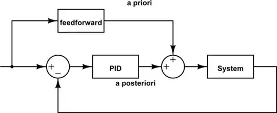
In such case, if you already know what the output should be (we say knowing 'a priori'), you can feedforward it. The controller has a role of 'a posteriori' aka corrector. If there is a mismatch of the 'a priori' output setting, the controller will correct the discrepancy.

Even if I find a linear relation between input signal and output signal, doesn't this only hold true for a certain load (i.e. a certain surface friction and incline)?

That's why the controller is needed.

schematic

simulate this circuit – Schematic created using CircuitLab

Marko Buršič
  • 23,562
  • 2
  • 20
  • 33
1

Even if I find a linear relation between input signal and output signal, doesn't this only hold true for a certain load (i.e. a certain surface friction and incline)?

Correct, the relation between applied voltage and speed will depend on the load on the motor.

If the answer above is yes, then what purpose does a PID controller even have in this system?

The fact that you can't predict the voltage-speed relationship in advance is exactly why you need a feedback controller (of which the PID is a very common example).

If you did know that a certain applied voltage (as generated by your PWM output) would always produce the same wheel rotation speed, then you wouldn't need a PID.

What the PID does is "observe" the actual wheel rotation speed, and increase or decrease, according to its control parameters, the applied voltage (PWM duty cycle) until the desired speed is reached. So you don't need to know the relationship in advance to get the wheel to run at the correct speed.

But of course the control loop may only be stable and effective in a limited range of load conditions, so you will need to adjust the control parameters to match the sensors and motors you're using and the load conditions where you need them to work.

The Photon
  • 126,425
  • 3
  • 159
  • 304
0

Re: units

The choice, as I see it, is whether to attempt to make the control tuning params in units of time^n (i.e. T_i rather than K_i, etc)

There must of course be a gain somewhere, and probably a number of limiting values and rates. A seemingly common industrial practice is have them relative to some [often cryptically specified] % of full-scale (FS), e.g. relative to FS-output for limits and rate limits, or (FS-output)/(FS-input) for gain.

In the case of PWM this actually becomes intuitive, as duty cycle is naturally unitless. For something like mbar/V for instance, I found that nondimensionalized tuning parameters actually confuse most customers. But still worth it in the long run, and it helps make more reuseable implementations.

Pete W
  • 1,207
  • 1
  • 5
  • 12