6

I was given a Trio CS 1554 Analog oscilloscope. It hasn't been turned on for at least 2 years, but probably a whole lot more.

Today I plugged it in and it turned on. It was usable for approximately 30 minutes. I then noticed that the trace line started to flicker, it then lost focus, finally a crackling sound was heard and it turned off.

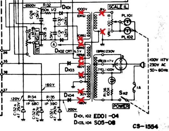
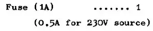
I got the service manual from here. I got to step 2, spot checking, on the trouble shooting flow chart. I was getting no power out of the transformer. I then checked the primary side of the transformer. There is a voltage selection switch that is connected to the power cable. The relevent part of the schematic is shown here:

power schematic

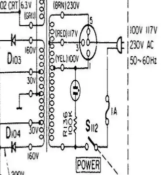
On the actual switch there is a 100 ohm resistor between the switch and the transformer. The resistor is shown here:

100 ohm resistor

I checked the resistor with my multimeter and it was open. There was also a dark spot in the middle, so it looked like it had failed.

I got a replacement resistor from the local electronics shop and replaced the broken resistor. The oscilloscope turn on. 10 minutes later, after I had closed it up, I heard a crackling sound and the trace line faded and it turned off again!

I haven't opened it up again but I have a few of questions.

There is no resistor on the schematic. What is the purpose of the resistor? Is it just for current protection? Or, is it to reduce voltage to the transformer? Would it run without the resistor?

Anyone have any tips for dealing with old equipment that hasn't been turned on for years? I dont have a Variac, so I cant apply a lower voltage. Are there any typical things that fail? I guess the electrolytic capacitors, especially around the power supply circuitry.

Thanks

zebonaut
  • 18,170
  • 4
  • 60
  • 104
Lance
  • 205
  • 2
  • 6
  • Is is R136 in the schematic that you are asking about? It is 100K ohm resistor. – Chetan Bhargava Jan 19 '13 at 08:35
  • Assuming it isn't R135 and a new 'mystery' component it seems like a bad design and would cause blowing the resistor instead of the 1A fuse. If your description is correct and it is hooked up that way it's like a down stream problem like caps as you say, and removing the resistor would probably just cause the fuse to blow first. – PeterJ Jan 19 '13 at 08:41
  • R136 is connected to a neon bulb. And the soldering looked like it was an after thought, perhaps the people who owned it first thought it was a good idea to stop fuses blowing! – Lance Jan 19 '13 at 08:46
  • I just checked now, and the fust blew this time! According to the service manual, its one of; defective power supply, high voltage diode, supply diodes, low voltage diodes, or smoothing caps. I'll have to carry out the troubleshooting tomorrow. – Lance Jan 19 '13 at 08:58
  • 1
    Resistor in series limits current, typically mainly turn-on and other spikes caused by capacitors, and also effectively acts as a kind of a fuse here. Since the scope seems to be working for a while before it blows the fuse, I would check the capacitors at first. – Al Kepp Jan 19 '13 at 10:28
  • 1
    @Al Kepp, fair point in one way, but in this case what looks like a 5W or 10W resistor could be dissipating 100W odd before the fuse blows in some circumstances. No doubt as the OP said the previous owner thought it was a good idea, but it's dangerous in my opinion and should be removed (as he / she's done now) and the real problem tracked down, which we both agree is most likely caps in the case of old equipment. – PeterJ Jan 19 '13 at 10:51
  • 2
    Voting to not close this question. While the motivation is repairing one specific model of oscilloscope, it is asked in a fashion that may be helpful for a much broader audience. This is one of the repair questions having the potential to teach something. – zebonaut Jan 19 '13 at 11:21

1 Answers1

3

Disclaimer: Troubleshooting this part of your oscilloscope is dangerous, because it's the mains connected part. Also, other parts of the scope, mainly the CRT supply and acceleration voltage, will present potentially lethal voltages. Having said this...

A resistor in series with the primary side of the power supply would be weird, doubly so because it isn't in the service manual / schematic. Using a power resistor like this to prevent the fuse from blowing first is, in my opinion, a fire hazard. The resistor may get really hot (and your picture looks like it really does!) before it fails open, causing nearby material to burn.

Also, the one resistor on the primary side should not be a cement block /power resistor, because the little neon lamp will likely use something like 100 k\$\Omega\$ and 1/4 W.

Any indication the resistor may have been added during an uncertain attempt to service the instrument?

Now, if the fuse blows after the resistor has been removed, the best way to attack the problem is to look at all the different power supply rails further downstream on the secondary side. Excessive ripple is a good indicator for capacitors having lost their rated value. Lifting one side of the capacitors and checking for leakage with an Ohmmeter or current-limited laboratory power supply is a good way of finding paths where excessive current may be flowing.

Note that a fuse blowing on the primary is often caused by too much current flowing somewhere right behind the secondary, i.e. diodes, capacitors, transistors for linear voltage regulation.

Edit:

To make sure whether it is the transformer itself or something on the secondary, test this:

Remove oscilloscope from mains supply (disconnect power cord).

Disconnect everything (except maybe one ground wire) from the secondary, taking notes which wire was connected to which pin on the transformer; all red crosses are to be opened for this test: CS-1554_Transformer

Note that some outputs have a high voltage!

Make sure that You don't have something really strange as two parts of the primary or secondary shorted when they should be open. Turn on, using a proper fuse, exactly as rated: CS-1554 Fuse rating as per Manual

If the problem is still there, you are likely dealing with a short between two windings, meaning your transformer is fried up beyond all repair (FUBAR). I fear this may really be what you're dealing with, because once a transformer has released some of its magic smoke, shorted windings are a common consequence (or may have bin the reason, to begin with). The "magnet wire" used for transformers is insulated with enamel. Once it burns, ...

zebonaut
  • 18,170
  • 4
  • 60
  • 104
  • Okay, I took the current limiting resistor off. Put a new fuse in. Replaced a couple of diodes. Everything seemed to be working. Except, I keep it on for a couple of minutes and the power transformer gets hot (I measured 80C). It starts smoking, and I can smell a glue-ish smell from it. I'm not sure if it is because it hasn't been turned on for a while, but I suspect it may be the reasons that resistor was put there. I may put the resistor back when I get home, and see how it goes. – Lance Jan 20 '13 at 02:20
  • The transformer should not start to smell if you use a fuse of the correct rating (which is always, really always, something you must make sure!). If the transformer starts to smoke: Very Bad. Editing my answer above... – zebonaut Jan 20 '13 at 11:26
  • Augh! It seems that it was the transformer! How frustrating. I doubt I will be able to get a replacement one on the cheap, and getting it rewound is probably going to cost me more than buying a new oscilloscope. So that was a sad end to a fun job. Thanks for the help – Lance Jan 22 '13 at 02:50
  • 1
    Maybe there's a similar scope somewhere on a flea market for cheap, and you can make 1 good one out of 2 bad ones... Good luck! – zebonaut Jan 22 '13 at 08:15