-1

I am currently reading through PC Sen's Principles of Electric Machines and Power Electronics (3e), and I continue to be confused by the tacit convention that the minus sign in Faraday's Law (and ultimately in the so-called "flux rule" derived therefrom) is omitted. For instance, consider the derivation of hysteresis losses (due to the rotation of magnetic domains in the iron) that he provides, as seen in the first two attached pictures below. Given how the polarity of e and i are defined in the second picture, I would have imagined that e should be negative when i is increasing. The only potential explanation I have is that the e of (1.26) is in fact an e due to a source that is driving the current, and we argue that it must be equal and opposite to the back emf induced by the changing flux (and thus changing current). But why is this so, if indeed I am right? Certainly the author does not mention this crucial detail.

Things are made more confusing when I go to another book. For example, in Analysis of Electric Machinery and Drive Systems by Krause et al., one finds the two pages attached in the last two pictures. Here, once again, there is no minus sign in front of the \$d\lambda/dt\$ term of equation (1.2-3), as would be expected given how polarities are defined for both voltages and fluxes.

What am I missing in both cases? Sorry for the wall of text, but I don't know how else to provide the requisite background for someone who's going to answer.

enter image description hereenter image description here. enter image description hereenter image description here

EE18
  • 427
  • 4
  • 14
  • 2
    I can't read your mind and I don't want to read all of what you quoted in some vague hope that I may accidentally trip on such an insight. Do you think you could find something more specific and concrete to ask about? – jonk Mar 19 '21 at 19:56
  • @jonk Sorry if the question is not clear, I had thought it was. My confusion is that, in both cases, there is no minus sign in the relevant "flux rule" equation and that appears to me incorrect given how the polarities of the corresponding voltages are defined in the given figure. – EE18 Mar 19 '21 at 19:58
  • Are you talking about magnetic circuits? – Miss Mulan Mar 19 '21 at 20:10
  • @MissMulan Yes, in the end these textbooks have done things in terms of the magnetic circuit approximation. But the crux of the issue for me is why, in both cases, there is no minus sign (reflecting Lenz's Law) in the relevant flux rule/Faraday's Law equation (1.26 in the first textbook and 1.2-3 in the second). – EE18 Mar 19 '21 at 20:12
  • @1729_SR Well, the sign is always such that it opposes the change. So, if a changing flux induces a non-Coulomb emf that impels a current, that induced current will be exactly arranged so that the magnetic field opposes the changing flux. The minus sign in Faraday's law reflects this fact. But I'm not putting much thought into this yet, so I may be still missing your question. – jonk Mar 19 '21 at 20:13
  • @1729_SR I just googled up a site that may help: [here](https://courses.lumenlearning.com/physics/chapter/23-2-faradays-law-of-induction-lenzs-law/). – jonk Mar 19 '21 at 20:17
  • @jonk No worries, thank you for taking the time to discuss. I follow you on what you're saying entirely, and must admit that I am a bit mortified that I'm not following what's going on in these textbooks. I minor in physics and so I am quite comfortable with electrodynamics. That is why I am perhaps making a mistake in interpreting the e of equation (1.26) as being an e due to the faradaic emf as opposed to e due to some undepicted source. At any rate and to be clear, *my confusion is that neither textbook includes a minus sign in front of the induced emf when I think they should*. – EE18 Mar 19 '21 at 20:19
  • @1729_SR Well, the physics is easy. Nature hates changing. It's as if all of the wave equations exist throughout all space-time at once and they resist finding new quasi-stable states, so it takes "work" to push uphill enough to then find a new locally stable wave-state. If you keep that in mind, then forces will always appear to counteract changes. That applies to most any situation. Signs will track that rule, religiously. – jonk Mar 19 '21 at 20:23
  • @jonk Indeed, as Griffiths says: nature abhors a change in flux. I understand the physics, I just do not understand why the textbooks are depicting the given polarities as they do. – EE18 Mar 19 '21 at 20:25
  • @1729_SR I'd be looking for a difference in their conventions. Keep in mind that things started out with no convention, at all. Then as more people pile into the topic and get a chance to apply their thoughts of organization and capturing useful ideas, that slowly over time conventions arise (through a concensus process.) If I started writing about some new idea I had, I might use one convention within my own writing. Someone else might gain a novel insight from reading me and realize that by turning the sign around, there is a broader convention into nearby areas of study. Don't be flummoxed. – jonk Mar 19 '21 at 20:29
  • @1729_SR Physics is immune to human conventions. Just focus on the basic ideas of physics, because that's all that matters. We humans have mathematics and we have conventions we use to communicate with each other. But they are human contrivances. If you keep only the basic ideas from physics in mind, the signs can be easily adduced. You only get confused when you focus on human conventions and lose sight of the physics going on. – jonk Mar 19 '21 at 20:32
  • @jonk Everything you've written is very true and good to keep in mind, but in this case conventions associated with classical electromagnetism (and electric machines as one of its applications) are well-established. I am certain that there is no issue of convention here. As I look at it more and more, I think I find myself increasingly convinced that there is an unspoken distinction being made by the authors between the induced faradaic emf and the emf due to an undepicted voltage source. I am hoping someone can read through it and confirm this. – EE18 Mar 19 '21 at 20:58
  • In physics there are 2 entities involved: the system and us. Signs in equations reflect the direction where energy goes. If energy comes from the system to us, we use + sign. If we put energy into the system, we use - sign. – Enrico Migliore Mar 22 '21 at 06:40
  • While I haven't read it myself, I can't help but wonder if a book on power at some point relates to the electrons and their mass and so forth. There is value in the opposite convention; we just happened to give electrons a 'negative' charge and stuck with it, thus establishing convention – Abel Mar 27 '21 at 04:12
  • @1729_SR Have a look at the sections "1 - A definition of potential difference" and "An example: the fake 'potential difference' across a coil" in my answer here: https://electronics.stackexchange.com/questions/506590/can-two-voltmeters-connected-to-the-same-terminals-show-different-values-circui (there is an inconsequential missing sign in one of the eqs, but the inversion of sign at the end is correct and might be what you're asking about. Also note that that explanation is agnostic in terms of the origin of the flux, so you'll have to fill in with the flux in the correct direction). – Sredni Vashtar Apr 05 '21 at 22:36

4 Answers4

0

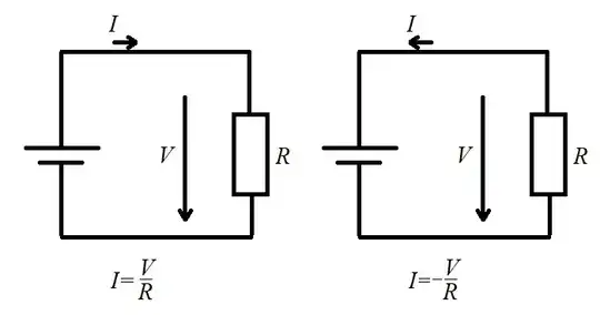
May be this simpler example will help. Here is a circuit with Ohm's law written below.

Ohm's law

First one is what you usually see. But there is nothing that restricts us from changing positive direction of current. And so we can have Ohm's law with a minus sign.

First thing that you do when analyzing electrical circuit is setup a system of coordinates (reference frame) by selecting positive directions of all values under consideration, that is by drawing arrows.

You can choose any direction of the arrows. You usually select the directions that help your intuition. Hence the minus sign in the Faraday's law. But you actually can't say is it minus or plus before you define arbitrary directions of the current, voltage, flux and also which way you wind the coil.

AlexVB
  • 393
  • 1
  • 9
  • Unfortunately the OP didn't understand basically that same argument in my now deleted post. BTW, you have the arrow directions for voltage drawn the wrong way around. – Andy aka Mar 25 '21 at 12:10
  • @Andyaka Why? When you walk against current you build up voltage. So voltage arrow goes from high potential to low. Do you use some other convention? – AlexVB Mar 25 '21 at 16:21
  • To be clear, I understood both @Andyaka's and your argument, but neither answers my question. They are each misinterpreting my question as though it's some basic misunderstanding of Lenz's law or how we use the passive/active convention in circuit analysis. Neither of these are confusing for me. – EE18 Mar 25 '21 at 22:41
  • Try and be clearer is my advice. – Andy aka Mar 25 '21 at 22:49
  • @1729_SR I think you shall just forget the minus sign in the Faraday's law. It serves no purpose apart from reminding you about the Lenz's rule. To really use the minus sign you need first to draw correct scheme for the experiment including emf and flux directions. Can you do that? I believe book authors don't even bother with the sign. They just know that reactance adds to resistance in a coil, not cancels it (hence 1.2-3). Answering your question, no, they are talking about induced emf, not source emf. – AlexVB Mar 25 '21 at 23:51
  • @1729_SR I would like to emphasize my point. Farday's law formula means nothing without the scheme in which \$e\$ and \$\Phi\$ are drawn with some certain direction. For your setup you may draw your own scheme and select positive directions for \$e\$ and \$\Phi\$ of your own and then deduce the sign using Lenz's rule. – AlexVB Mar 26 '21 at 00:05
0

You are right that Lenz's law states that the induced voltage of an inductor \$e=-N\frac{d\phi}{dt}\$. In this equation, \$e\$ is the total voltage drop across all the inductor windings, which must be driven by an external voltage source. If the external voltage source is at the terminals of the circuit, then its voltage would be equal to \$e\$.

enter image description here

The polarity of the voltage drop is defined so that it already opposes the driving voltage source (as shown above). Since the polarity of \$e\$ is already defined so that it opposes the voltage source, \$e\$ is positive. By defining the polarity in this way, are multiplying \$e=-N\frac{d\phi}{dt}\$ by -1.

Sidenote: all inductors behave in this way and have a voltage drop \$V_L=L\frac{di}{dt}\$, where \$L=\frac{N\phi}{I}\$. In order to model an inductor this way, we assume that a linear B-H curve so that \$I\$ and \$\phi\$ are directly proportional.

Brad
  • 1
  • 2
  • I believe Faraday's law says nothing about external voltage. – AlexVB Mar 27 '21 at 11:57
  • You're right. I meant to say that there needs to be an external source driving the inductor. windings. If you're looking at Figure 1.12a, then the magnitude of the voltage source would be the same as \$e\$ – Brad Mar 27 '21 at 17:20
0

Let's assume i is increasing (in clockwise direction in your figure) at time t around its neighborhood .

Based on above assumption , we can find what will be the linked flux through​ coil . And according to Faraday law there will be an induce electric field which causes an induce emf and this induce emf causes a current .

But what should be the direction of current due to induce emf?

From ,Lenz's law -it should be opposite of i because it try to oppose the increasing of i.

So we can say at time t a current Ia is there solely due to induce emf (Ia>0 ,in anticlockwise direction from your figure).

So , $$i= -I_a+I_b$$ , where Ib (>0) is current (solely due to Electrostatic field).

Let's calculate, work done by total electric field (Electrostatic +induce electric field) on moving an unit positive charge along the path of wire from left end of coil to right end of coil = $$iR= (-I_a+I_b)R=-I_aR+I_bR=-\frac{d\phi}{dt}+I_bR$$ Since$$ I_aR=\frac{d\phi}{dt}=L\frac{di}{dt}>0 $$because we assumed already that i is increasing function around neighborhood of t.

Now , let's calculate work done on unit positive charge by external force along the path of wire and starting from -ve terminal of battery moving in clockwise direction to reach again at the same point (360 degree rotation)=W=work done against Electrostatic electric field +work done against induce electric field =V-iR

We know ,work done against Electrostatic electric field =0 because Electrostatic electric field is a conservative field Hence

Work done against induce electric field =Ia R (+ve because path is from left end to right end of coil (since unit charge moving in clockwise direction) =$$\frac{d\phi}{dt}=L\frac{di}{dt} $$

Hence,$$Ia R=V-iR \implies \frac{d\phi}{dt}=V-iR\implies V=iR+\frac{d\phi}{dt}$$

user215805
  • 1,144
  • 1
  • 7
  • 18
  • @1729_SR I think ,I address your confusion precisely but still if you have any question you can ask about it , because without your inputs ,we are going nowhere! – user215805 Mar 27 '21 at 21:54
0

You need to verify this hypothesis :

By convention we always consider the current flowing from positive to the negative, although in reality it is the opposite.

https://www.mi.mun.ca/users/cchaulk/eltk1100/ivse/ivse.htm#:~:text=Conventional%20Current%20assumes%20that%20current,negative%20terminal%20of%20the%20source.&text=Electron%20Flow%20is%20what%20actually,positive%20terminal%20of%20the%20source.

This leads to discrepancies on text books, where electrical engineering textbook will usually consider the flow as positive to negative while more scientific ones will consider the other, resulting in discrepancies in polarity, the minus sign.

Damien
  • 7,827
  • 1
  • 12
  • 29