19

I'm designing a circuit to switch a 240V AC load and haven't done a lot with AC power control before. I'm planning to use a Fairchild MC3043-M optically coupled TRIAC driver along with a BT138-600 NXP BT138-600 TRIAC. Referring to the following diagram from the datasheet:

enter image description here

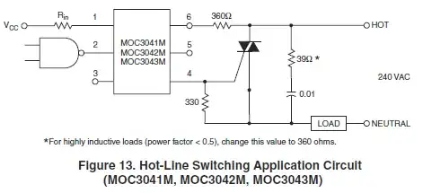
The comment is made that for highly inductive loads (power factor < 0.5), change this value to 360R. One load I'm switching is an AC fan (0.8A) which is obviously inductive although I have no idea of the power factor likely, and the other is a router using a 20W switching supply.

My question is to make the circuit universal considering it's not for a commercial product design and I may use for other purposes in the future is there any disadvantage to always using a 360R (well guess I'll use 390R) other than needing a higher power rating for the resistor? Also any hints on calculating the power dissipation through the resistor assuming a 5A load which is what I'm planning to use as a fuse value?

PeterJ
  • 17,131
  • 37
  • 56
  • 91

2 Answers2

20

TRIACs switch off at (near) zero current. It is common for switches that switch passively at zero current to experience a voltage step that will cause circuit parasitic inductance and capacitance to ring. There are 2 problems:

  • The peak voltage of the ringing can exceed the rating of the TRIAC.
  • TRIACs also have a maximum rated \$\frac {\text {dV}} {\text {dt}}\$ that if exceed will cause the TRIAC to spontaneously trigger.

A snubber, like in your Figure 13 would be used to dampen energy in the parasitic elements. The inductance will be in the load (\$L_L\$), since it is common to use TRIACs for motor control which are inductive. The parasitic capacitance is the capacitance of the TRIAC \$C_T\$. The snubber works by providing an impedance match to the \$L_L\$ \$C_T\$ resonance. Snubber resistance \$R_s\$ is added to the load resistance \$R_L\$ to match characteristic impedance Zo = \$\sqrt{\frac{L_L}{C_T}}\$. They tell you to use a higher value for \$R_s\$ for loads with higher inductance because Zo increases with increasing \$L_L\$.

Typically you will want to use a value for \$C_s\$ that is 10 times \$C_T\$. For a medium sized TRIAC (one that handles about 10A) \$C_T\$ is often about 100pF. I didn't see a spec for \$C_T\$ in the datasheet for the NXP BT138 TRIAC. The best value for the \$R_s\$ is Zo-\$R_L\$.

Here is a link to an app-note that provides more detail.

Mels
  • 1,126
  • 9
  • 19
gsills
  • 7,133
  • 16
  • 22
  • 1
    The ST App Note is AN437 RC snubber circuit design for TRIACs, as they tend to change the location of things. Here is the current link: http://www.st.com/st-web-ui/static/active/en/resource/technical/document/application_note/CD00004096.pdf?s_searchtype=keyword – Michael Pruitt Aug 02 '13 at 20:19
  • 1
    Edited post (pending review) to include new link – Mels Dec 04 '13 at 12:20
  • Thanks @MichaelPruitt for keeping the app note link relevant to the answer. – gsills Jan 12 '14 at 23:47
  • 1
    Thanks @Mels for helping to keep app note relevant and easy to find. – gsills Jan 12 '14 at 23:49
1

When the TRIAC is switched off the capacitor and the inductivity will be an oscillator. The resistor will attenuate the oscillation. If R is higher, the attenuation will be much higher.

For the power dissipation you can calculate the reactance of the capacity and calculate the maximum current when the TRIAC is switched off. Then you can calculate the power loss of the resistor.

Philipp
  • 126
  • 1
  • 3