0

enter image description here

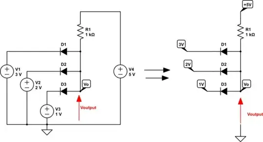
The diodes in both circuits are ideal. I drew the circuit on the right to make a comparison. As the answers given for V and I in the circuit on the left are 1 V and 4 mA, this means D1 and D2 are not conducting while D1 is. I have not really seen a ground mark placed beside the circuit, so I can't be sure what it means. I can only guess, according to the given answers that it means the whole branch D1 is in is connected to the ground, thus meaning there is 0 voltage across D1, is that so?

winny
  • 13,064
  • 6
  • 46
  • 63

2 Answers2

2

Look at this,

schematic

simulate this circuit – Schematic created using CircuitLab

When on the left you have a full schematic and on the right a simplified one.

And this means that your right schematic is wrong (not equivalent with the left circuit).

schematic

simulate this circuit

And here you can read about GND How to find Voltage based on reference nodes?

G36
  • 13,642
  • 1
  • 18
  • 33
0

@Xuanhan Zhu: The diagram on the right makes no sense with regard to the connection of the diodes. With the voltage specifications on the anodes, all diodes are in reverse direction and do not carry any current. From my point of view, the scheme on the left is the correct one.