First of all, I suck a bit at math, and I'm no electronics genius, so the stuff I do is for fun and for learning purposes...
I'm working on a buck converter circuit to convert my USB Vbus 5V to 3.3V. I've selected the AP5100 and finding it quite challenging to figure out the correct values on some of the components.
The datasheet neatly specifies the values for R1(49.9kΩ) and R2(16.2kΩ) in Table 1 on page 6, to establish an output voltage of 3.3V, but I'm finding it a bit of a train smash understanding how to calculate the inductance value for the L1 inductor. The datasheet indicates 3.3µH on page 2, Figure 3:
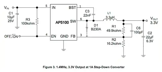
I'm wanting to understand better how the 3.3µH was calculated, and if this is in fact the correct value for my application.
Now back to the datasheet, the formula for calculating L is stated as:
$$ L = \frac{Vout \times (Vin - Vout)}{Vin \times \Delta IL \times fSW} $$
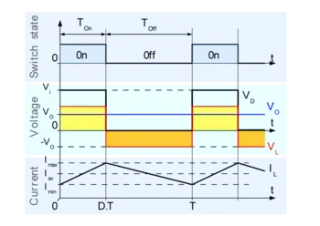
Where ΔIL is the inductor ripple current, and fSW is the buck converter switching frequency.
The datasheet states:
Choose the inductor ripple current to be 30% of the maximum load current. The maximum inductor peak current is calculated from:
$$ IL(MAX) = ILOAD + \frac{\Delta IL}{2} $$
Alright, this is where I'm horribly lost, and trying my best to wrap my tiny brain around the value.
I know the following:
- Vin = 5V (USB Vbus)
- Vout = 3.3V
- fSW = 1.4MHz
- I = 2.4A (I think)
How does one determine the ΔIL (ripple current) in order to get to the inductor value?
My formula should look something like this in the end, right?
$$ L = \frac{3.3V \times (5V - 3.3V)}{5V \times \Delta IL \times 1.4MHz} $$
But what is ΔIL?
Also I thought the buck converter was supposed to allow a range of inputs for Vin, in the case of this one, 4.75V to 24V?
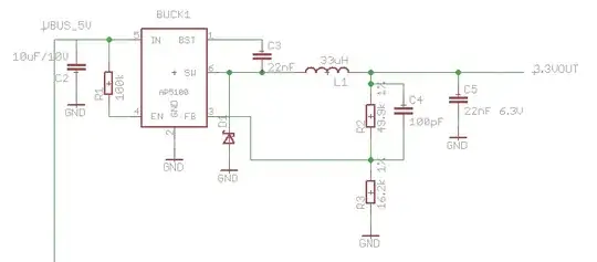
Here's my schematic I'm drawing in Eagle CAD: