35

So I've been looking through and going through my Digital Computer Electronics book, and I came to this... It seems so simple and I understand the "point" of it, but I'm not sure I understand exactly how it works.

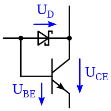
"In a Schottky transistor, the Schottky diode shunts current from the base into the collector before the transistor goes into saturation."

I guess this part confuses me above ^^^

http://en.wikipedia.org/wiki/Schottky_transistor

From what I gather the Schottky Diode has a forward voltage of .25 V... So it's taking .25 V out of the Input Line (coming from the left of the picture) and putting THAT into the collector... So it'll just take less time to switch... Because there is .25 V less coming in the base? Or is adding .25 V to the collector so when the Transistor turns "on" it'll already have a little bit flowing through it (since .25 V isn't enough to actually flow through when it's off?)? Wikipedia entry is confusing. I feel pretty stupid for asking such a simple question lol.

enter image description here

rszalski
  • 109
  • 5
  • 3
    You need to sort out your notions of voltage and current (voltage doesn't flow). Also, units are case sensitive, the symbol for Volt is V (upper case). – starblue Jan 15 '13 at 10:30
  • 1
    One hurdle I had to jump to understand Schottky transistors is that the difference between the collector-emitter voltage is less than the base-emitter voltage in a saturated transistor. (\$V_{ce} \approx 0.2V\$, compared to \$V_{be} \approx 0.6V\$, check the datasheet for more accurate values.) This is how the Schottky diode manages to ever get forward biased. – Phil Frost Jan 15 '13 at 16:42
  • 3
    @starblue, Just to make sure OP gets the right habits, I'll clarify that the symbol for volts is an upper-case "V", but the word *volt* itself is not capitalized. – The Photon Jan 25 '13 at 19:34
  • @The Photon Yes, sorry about that, it shows I'm not a native speaker. – starblue Jan 25 '13 at 21:13
  • 2
    @starblue, lots of native english speakers actually get this wrong too. – The Photon Jan 25 '13 at 21:47
  • Well "volt" is named after [Alessandro Volta 1745-1827](https://en.wikipedia.org/wiki/Alessandro_Volta). Being a proper name, should it be capitalized? "Hertz" is always Hz... – rdtsc Aug 02 '19 at 13:27

2 Answers2

27

Oli's answer is good on the mechanics of what happens : Without the diode, as increasing base current turns the transistor on harder, the transistor Vce falls below Vbe, until the transistor saturates at Vce=0.2 or even 0.05V.

And with the diode present, as Vce falls below about 0.45V ( 0.7V minus the diode 0.25V forward voltage) the diode will start stealing the base current, preventing the transistor from saturating. (I'm not sure why Oli says this occurs at Vce=0.7V, perhaps he was using an "ideal diode" in his simulation).

But what's missing is the why:

When a transistor saturates, the base region is awash with extra carriers, and virtually no collector potential (Vce close to 0) to attract them out of the base. Therefore when you switch off the base current, the transistor remains conducting for an appreciable period of time before turning off.

Preventing it from saturation in this manner (by removing the excess base current) means it can switch off much faster, while leaving the switch-on time unaffected.

Adding this hack to 74 series logic basically tripled its speed (74S) for the same power, or allowed significantly lower power (74LS) for the same performance.

  • I said this occurs at around 0.7V since this is roughly the base-emitter drop of a bipolar transistor. The schottky diode forward voltage is tiny at low current levels such as in my simulation, so it adds almost nothing (if the base resistor was lower, then it would occur at a lower voltage such as the 0.45V you mention). You can see this (the diode beginning to turn on at around 0.7V) in the simulation in my answer. – Oli Glaser Jan 15 '13 at 12:47
  • Okay, so for tiny excess currents Vschottky will be much less than 0.25V. But then, Vbe is more like 0.6V for sufficiently small currents. But the form of the equation is still Vce=Vbe-Vschottky, and will tend towards 0.4V as the input current increases. –  Jan 15 '13 at 12:52
  • Yes, I mentioned this in the second paragraph "when the collector voltage drops below Vbase - Vschottky" (it should be really be Vbase-emitter, but ground is implied) Though it wasn't presented as a formula, I maybe should have made this clearer. – Oli Glaser Jan 15 '13 at 12:55
  • Okay I edited my answer to include some clarification. – Oli Glaser Jan 15 '13 at 13:51
  • Heres a question: How is having the Schottky diode there any different than simply tying the base to the collector directly? If you did that, V_ce would always be around 0.6-0.7 V, which would also keep the transistor in the active region. –  Jan 16 '13 at 18:21
  • 1
    @Sauron : If you tie the base directly to the collector, you no longer have amplification; you have turned the transistor into a diode! –  Jan 25 '13 at 11:00
24

What happens is:

As the base voltage rises, the transistor begins to turn on and it's collector voltage drops (assuming it has a collector resistor or similar current limiting element)

Normally a typical bipolar transistors saturation voltage is around 200mV or less. When the collector voltage, Vce drops below Vbe - Vschottky though, the schottky starts to conduct (now being forward biased) and the base current starts to flow through it into the collector. This "steals" current from the base, preventing the transistor turning on more and the collector reaching it's saturation voltage.
The system will reach a state of equilibrium, since the transistor can't turn on any more without it's base current dropping (you could see it as a form of negative feedback) and will settle just around Vbe-Vschotkky (e.g.~700mv-450mV as opposed to ~200mV)

So, to clarify things, the formula for Vce is:

Vce = Vbe - Vschottky

If we have this circuit and apply a ramped voltage from 0-2V:

Schottky Transistor

We get simulation results like this:

Schottky Transistor Sim

Note that when Vcollector drops below ~700mV, the Schottky begins to conduct and the collector voltage levels out at around 650mV.

If we remove the Schottky, then:

Simulation with no Schottky

We can see the collector drops all the way to 89mV (I used the cursor as it's hard to see from the graph)

Oli Glaser
  • 54,990
  • 3
  • 76
  • 147
  • This sorta makes sense......but I guess I don't understand what you mean that when the transistor turns "on" the collector voltage is dropping, when the transistor is "on" shouldn't Alot of voltage be flowing through the collector through the emitter? Unless im not understanding how a transistor works....but doesn't a voltage applied to the base allow voltage to flow through the collector and out the emitter? I guess it confuses me that when the transistor is "on" why would the voltage be lower on the collector? –  Jan 15 '13 at 19:48
  • 2
    See @starblue's comment on this one - voltage doesn't flow, it's a potential difference between two points. It's the current that increases as the transistor turns on. For a quick water analogy; think of a battery like the pump, the pressure it creates the voltage, and the water flowing through the pipes the current. The transistor acts a bit like a valve in the pipe to control the current. I'd maybe grab a basic electronic book (Practical Electronics for Inventors is pretty good) and work through the first few chapters, then come back to this. – Oli Glaser Jan 16 '13 at 03:47
  • 1
    To follow from the water analogy - the resistor R2 is like a narrowing in the pipe, creating a pressure difference (voltage) across it. As the transistor opens/closes, the pressure difference across it increases/decreases. When the transistor is closed the pressure/voltage is at it's *highest* (it would be at the full pump pressure as there is no water flowing) As the transistor opens and water/current fows, the pressure/voltage across it drops, so the pressure/voltage at the junction of R2 and the transistor drops. Sorry if this confuses you more, just trying to paint a rough picture. – Oli Glaser Jan 16 '13 at 03:55
  • I think that makes sense, with the transistor closed a bunch of "Backpressure" aka VOltage is building up behind it, and once it opens the PRessure (voltage) is released until it goes down to .2v or whatever minimum it hits. correct? –  Jan 16 '13 at 04:51
  • Quick question however....since 12v is at the Collector of the transistor when it's turned off.....does this heat up the transistor at all...or since it's not receiving current i guess it doesn't matter? –  Jan 16 '13 at 05:30
  • @Sauron : Right : 12V * 0 current = 0 power, 0 heat. 0.2V*current = little power, little heat. The problem is _during_ switching : 6V * current/2 = power and heat. One more reason to switch fast : stay cool. –  Jan 16 '13 at 09:18
  • Ok, makes sense since when it's turning on it has full current but a mid voltage for a short amount of time.........gotcha. –  Jan 16 '13 at 17:39
  • Sauron - on your comment aboout the "backpressure": yes, you have got the idea. Seems like my random waffle was of some use after all ;-) @Brian's comment/answer is particularly relevant about the actual reason for the schottky, to switch fast (don't let the transistor saturate) Plus (on his comment above) keeping the transistor out of the "midpoint" (max power dissipation) region as much as possible is a big concern when designing digital/switching circuits. This is why you will see e.g. pulse width modulation (PWM) used to dim a lamp instead of a gradual turn on/off) – Oli Glaser Jan 16 '13 at 19:02