0

I have a bunch of spst-no buttons each with an led inside. I've just hooked them up to a MAX7219 and they are very dim (when hooked up directly to the microcontroller they're fine).

My guess is the buttons all have resistors inside, but they're all sealed up so there's no way to know without destroying them.

If they all have their own individual resistors, can I get away with removing the single resistor before the max7219 (or reduce it down from 10k to a lot less?)

Edit: To clarify, If I remove the resistor before the MAX7219, is it likely to break the chip in some way (considering that there are resistors before each LED)?

Here's a quick and dirty simplified schematic. Is it safe to remove R1 if R2 exists? My understanding is that without a resistor, an LED is likely to burn out. If that's what happens without R1, then the MAX7219 will be fine with a lower resistor value and I can probably play around a bit to try and improve the brightness of the LED. Voltage coming in is I think 5V (from a usb connection)

schematic

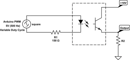
simulate this circuit – Schematic created using CircuitLab

This is the datasheet for the button: https://www.tme.eu/Document/9b8f20f491475d99dbf596e24530b068/r13_523.pdf - I'm guessing 100M Ohms "Insulation resistance" is the total of the resistor + led?

Dan Forever
  • 243
  • 2
  • 8
  • You had best show your schematic. 10K sounds like a pullup resistor, not an LED series resistor and the multiplexing scheme will make it dimmer by its very nature. – Spehro Pefhany Feb 25 '21 at 16:09
  • For the most part, the design is identical to that listed here: http://wayoda.github.io/LedControl/pages/hardware My buttons/leds are laid out in a 4x4 matrix – Dan Forever Feb 25 '21 at 16:11
  • In my testing with regular LEDs, they were bright – Dan Forever Feb 25 '21 at 16:17
  • If you want to test if they have an internal resistor, you can measure the forward voltage at a number of different currents (from a current-limited PSU), and then see if that matches up with the I-V curve of a diode, or a diode with a resistor in series. – Hearth Feb 25 '21 at 16:50
  • But the question topic does not match the description. Which one you mean, are you asking about ISET pin resistor, or possible resistances inside the chip? – Justme Feb 25 '21 at 17:20
  • Reducing Rset to 0 will enable more voltage to the current limited LED – Tony Stewart EE75 Feb 25 '21 at 20:42
  • @TonyStewartSunnyskyguyEE75 But will it damage the MAX7219 as it passes through? – Dan Forever Feb 25 '21 at 20:48
  • how could it if you tested it with a simple LED. Its just a (disabled) active current limiter with your switch external R – Tony Stewart EE75 Feb 25 '21 at 21:37

1 Answers1

2

Those pushbuttons have a LED with resistor, as those are meant to be driven at 12V.

Driving it with the MAX7219 cannot drive the pushbutton LEDs very bright, because it is meant to be used with 5V supply.

As per the question itself, the datasheet does not say what is the minimum resistance, but it does not matter. No matter how much you want current out of it, it still can't drive LEDs that have built-in resistors for 12V use. Usually the LEDs are rated at 12V 20mA.

This is also indicated by the curve "SEGMENT DRIVER OUTPUT CURRENTvs. OUTPUT VOLTAGE" on the datasheet page 4. For all three resistor values, at the output voltage of 5V, current has dropped to about 5mA anyway.

Justme
  • 127,425
  • 3
  • 97
  • 261
  • Yes, I know that, but it's not the question I asked – Dan Forever Feb 25 '21 at 20:47
  • I updated the answer. Datasheet does not tell that, but even if zero ohms would be allowed, the chip and the LEDs in the button are still incompatible (they should be 20mA LEDs at 12V) – Justme Feb 25 '21 at 21:08