I'm interested in measuring the back-EMF of a motor to determine a motor's speed because it's cheap and requires no additional mechanical parts. How can I measure the back-EMF when I'm driving the motor?
Asked
Active
Viewed 2.9k times
26
-
+1. Just to pile on more information: http://www.acroname.com/robotics/info/articles/back-emf/back-emf.html – Nick Alexeev Mar 26 '13 at 18:55
1 Answers
27
One way to do this is to briefly stop driving the motor, long enough to let any residual current from the driving voltage die down, and then simply measure the voltage. The time it takes the current to settle will depend on the inductance of the windings. This is simple to understand, and the undriven interval can be made quite short, but this has obvious disadvantages.
Another method involves a clever use of Ohm's law. A motor can be modeled as a series circuit of an inductor, a resistor, and a voltage source. The inductor represents the inductance of the motor's windings. The resistor is the resistance of that wire. The voltage source represents the back-EMF, and it is directly proportional to the speed of the motor.
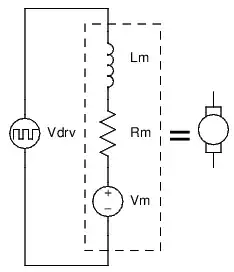
If we can know the resistance of the motor, and we can measure the current in the motor, we can infer what the back-EMF must be while the motor is being driven! Here's how:
We can ignore \$L_m\$ so long as the current through the motor is not changing much, because the voltage across an inductor proportional to the rate of change of current. No change in current means no voltage across the inductor.
If we are driving the motor with PWM, then the inductor serves to keep the current in the motor relatively constant. All we care about then, is really the average voltage of \$V_{drv}\$, which is just the supply voltage multiplied by the duty cycle.
So, we have an effective voltage we are applying to the motor, which we are modeling as a resistor and a voltage source in series. We also know the current in the motor, and the current in the resistor of our model must be the same because it is a series circuit. We can use Ohm's law to calculate what the voltage across this resistor must be, and the difference between the voltage drop over the resistor and our applied voltage must be the back-EMF.
Example:
motor winding resistance \$ = R_m = 1.5\:\Omega\$
measured motor current \$= I = 2\:\mathrm A \$
supply voltage \$= V_{cc} = 24\:\mathrm V \$
duty cycle \$ = d = 80\% \$
Calculation:
24V at an 80% duty cycle is effectively applying 19.2V to the motor:
$$ \overline{V_{drv}} = dV_{cc} = 80\% \cdot 24\:\mathrm V = 19.2\:\mathrm V $$
The voltage drop over the winding resistance is found by Ohm's law, the product of the current and winding resistance:
$$ V_{R_m} = IR_m = 2\:\mathrm A \cdot 1.5\:\Omega = 3\:\mathrm V $$
The back-EMF is the effective driving voltage, less voltage across the winding resistance:
$$ V_m = \overline{V_{drv}} - V_{R_m} = 19.2\:\mathrm V - 3\:\mathrm V = 16.2\:\mathrm V $$
Putting it all together into one equation:
$$ V_m = dV_{cc} - R_m I $$
Phil Frost
- 56,804
- 17
- 141
- 262
-
1A point that's worth noting is that, except to the extent that an inductor has *parallel* resistance or other leakage, the average voltage across an inductor over any given time interval must be proportional to the difference in current between the start and end of that interval. If an inductor has the same amount of current flowing through it at the start and end of some time interval, the average voltage across the inductor must be zero. That rule applies both to discrete inductors, and also the inductor one models as being in series with an ideal motor. – supercat Jan 14 '13 at 20:06
-
@supercat: hm, interesting point. I can see how I could use that to further justify ignoring the inductor, but then I thought of something else. If the current actually is changing (during periods of load change or speed change, perhaps) this would introduce an error into this method, wouldn't it? I wonder if this is significant enough to merit consideration. – Phil Frost Jan 14 '13 at 20:22
-
1Also, note that if one is PWM'ing a motor at a decent frequency, efficiency will be best if the current in its inductance does *not* die down between cycles. Rather than open-circuiting the motor, short-circuit it unless or until the current drops to nothing (hopefully the PWM rate will be fast enough that it won't). If one short-circuits the motor long enough, the current will fall to nothing and then reverse. Reverse current will kill efficiency, so open the circuit at that point (or short through a transistor that only allows one direction of current). Note that... – supercat Jan 14 '13 at 20:30
-
1...if the stall current exceeds the amount one's supply can output without sagging, PWM'ing the motor may actually *increase* the available starting or slow-speed torque. Note also that if the motor is turning faster than the speed "requested" by the PWM, some of the excess energy will be dumped back into the supply (good for efficiency, if one can safely harness it). – supercat Jan 14 '13 at 20:36
-
BTW, one generally doesn't have to worry about motor inductance turning a change in motor current into an erroneous voltage. It may cause some individual readings to be off, and could potentially lead to oscillation, but it's but one of many factors for which would cause oscillation in an uncompensated feedback loop, and which may, along with the others, be corrected by using a properly-tuned PID loop. – supercat Jan 14 '13 at 20:49
-
1I am not a specialist, but I don't think you can just assume your current won't change, and you can just ignore your inductance that easily. External loads will produce torque and this torque will produce a change in current. Also the PWM itsef will make a change in current in the motor...yes the inductance will keep it "average" but this won't be a flat line, also it makes it average by creating voltages. How much will this really impact your project? Well, I can't say, it totally dependent on the motor itself and the load, so this will vary drastically from project to project. – mFeinstein Dec 21 '14 at 03:52
-
@mFeinstein having actually implemented and tested this method, I can say that while both the effects you mention do exist, they *can* be ignored. If you require extreme precision in speed regulation then you should be using a servo. The benefit of this method is simplicity. – Phil Frost Dec 21 '14 at 14:37
-
1As I said I think this is much application dependant... Did you use it in big motors and high inertia loads? It could have worked really nicely for your application but I can't say for all other out there... Yes servos are better... If you can use them.... I have seen control of big loads with big noisy brushed motors and every variable counted in that application... But yes, for simple stuff this can work, I never ruled it out, just keep an eye on things if it doesn't – mFeinstein Dec 21 '14 at 14:43
-
@mFeinstein Does a small electric car count as a big motor and high inertia load? – Phil Frost Dec 21 '14 at 21:48
-
Probably I guess :) , I think it depends a lot on the motor, the inductance and the precision of control that you need, on an ampflow for example every bit of information makes the difference – mFeinstein Dec 22 '14 at 00:19
-
Why not just measure the voltage drop across a BLDC motor while its running with a multimeter and multiply by Kv to estimate the speed of a motor? Why do you need to measure current? – techSultan Jun 23 '17 at 15:14
-
1@techSultan A brushless motor does open some possibilities not discussed here. – Phil Frost Jun 23 '17 at 18:13
-
2This method is discussed in more detail in a IEEE paper: http://ieeexplore.ieee.org/stamp/stamp.jsp?tp=&arnumber=4314629 – Amir Samakar Oct 30 '17 at 21:20