7

This is about designing a circuit that can control multiple LEDs synchronized to music or sound, as simply as possible. I am looking for some conceptual ideas to start out with, not a complete circuit design or anything.

My question is inspired by this YouTube video (now those are heels to kill for!)

I have read the question Flash an LED to music but it does not begin to address a requirement like those shoes.

I realize that there are many different and increasingly complex ways of achieving the desired result, but I am looking for the simplest approach, even if it is not the cheapest, and not the most precise. Also, I am not looking for a ready-made pair of shoes that has this (though if there are any, would be interesting to know about them).
Kevin Reid
  • 7,444
  • 1
  • 25
  • 44
Aashima A
  • 213
  • 1
  • 3
  • 7
  • Explain what you mean by "LEDs synchronized to music". Just the volume? Does the frequency matter? Differnt color LEDs doing different things? How much power available? No, I'm not going to chase down a video to get basic necessary information to understand a question. If you can't explain what you want in a paragraph or too, then you haven't thought about the problem well and this isn't a real question. – Olin Lathrop Jan 14 '13 at 14:08
  • considering conversion sound to light: this might not really help you but check out Neil Harbisson on TED talks. He is a cyborg i.e. he can see sound. ted.com/talks/neil_harbisson_i_listen_to_color.html – sheetansh Jan 14 '13 at 14:41
  • From the video and others like it, say 3 LEDs, one for bass, one for treble and one for the rest, with the intensity of each LED varying by the volume of sound in the respective range. Pulsing from maximum to minimum with say half-second to a second of averaging. The specific colors I can deal with, not relevant to my question. Power: A good pair of high heels would allow me to have two C-type or 4 pencil cells or a fairly big rechargable battery in each heel. If there are any other questions, I can answer those too. I wonder what I did to deserve this sharp tone? Explain, I learn fast. – Aashima A Jan 14 '13 at 15:29
  • 1
    It looks like a lot of people are interested in high heels with LEDs in them. There's a business opportunity *down there* somewhere ;-) – Anindo Ghosh Jan 14 '13 at 16:11
  • @AashimaA Ignore the sharp tone, you'll learn to appreciate Olin's bluntness xP – Shamtam Jan 15 '13 at 00:36
  • @Shamtam I think some people are lonely and like the attention rudeness gets them. It's also fun when they make assumptions about others. – Aashima A Jan 16 '13 at 03:21

5 Answers5

4

Depends on your meaning of simple. @Tcrosely answer gives a good example, a simple passive color organ, all parts that can be found through hole. Using resistor/capacitor pairs as bandpass filters.

Or you might think a microcontroller solution is simpler. Which there are three ways of doing.

Completely in software (FFT libraries for Arduinos/MSP430/Pics), using another chip to capture the audio and turn it into digital information you can use (The MSGEQ7 + microcontroller is a popular version of this), or dedicated chips (All do three band, bass/mid/treble, with adjustable cross over points, or randomization of the LEDs)

TI's/NatSemi's LM4970 (most ""hobbyiest"" ""friendly"" package) or other's in their Boomer family (really small SMD). The LM4970 needs to only be enabled by i2c from a microcontroller, while some of the Boomer chips have an auto on mode. AMS's AS3665 and AS3668, both which have auto audio sync mode. ISSI's IS31FL3193,IS31FL3196, and IS31FL3199. Same as the LM4970, needs a simple i2c on command.

Simple really depends on your experience and how easy you can get parts. A dedicated chip method would need a lot less parts or board space than a passive component color organ, and can be powered by a lower voltage.

Chetan Bhargava
  • 4,612
  • 5
  • 27
  • 40
Passerby
  • 72,580
  • 7
  • 90
  • 202
  • Thank you, I am going with the LM4970 option. That's a terrific find. – Aashima A Jan 15 '13 at 15:14
  • @AashimaA just beware the package size. It's a leadless 0.5mm pitch package. You can deadbug it with patience (I have) but it's meant to be done with reflowing (Either an oven or hot air gun or similar). The other chips are bga, that's what I meant. I wish they were simple soic or even tssop, but nope, very tiny package. See: http://www.robotcraft.ca/webshop/images/LEDControler-01-L-UP.jpg – Passerby Jan 15 '13 at 17:05
  • This is an interesting IC! Would have never guessed there is enough demand for this to make a specialized chip for it. – dext0rb Jan 15 '13 at 19:18
  • @Dextorb not just one, but multiple companies, with multiple chips. – Passerby Jan 15 '13 at 20:20
  • @Passerby I'm not planning to deadbug it, already ordered a prebuilt breakout like the robotcraft.ca one for first experiment. Later it'll be skillet cooking on fabbed boards. – Aashima A Jan 16 '13 at 03:19
  • @AashimaA Let me know if you end up with any extra boards you want to give away ;D – Passerby Jan 16 '13 at 05:43
  • @Passerby I'll put in a panelized order for around 3 boards each pass, so it might happen. – Aashima A Jan 16 '13 at 06:14
3

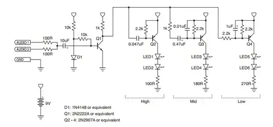
What you are looking for is called a "color organ". I did some looking around on the net, but most circuits used a combination of op-amps and drivers and were much too complicated (IMO) for your needs. But I found the following one which appears simple enough:

enter image description here

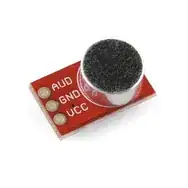
It is designed to run off a 9v battery, but perhaps you could use three 3v coin cells in series. It is also designed to take its input from a MP3 player such as an iPod; for use with an electret microphone the author recommends one with a pre-amplifier like this one:

enter image description here

It runs off of 2.7v to 5.5v, so you could tap off of the first 3v coin cell to power it.

tcrosley
  • 47,708
  • 5
  • 97
  • 161
2

To address the conceptual ideas:

  • You need a very simple and small microphone, an electret mic would do for this.
  • A small power source, like a coin cell or two.
  • A couple of transistors, and LEDs
  • Some basic filtering that directs e.g. bass frequencies to one colour LED and higher frequencies to the other (you can have many filters if you want more LEDs)

This could be done entirely in a simple analog fashion, but you could also consider a small microcontroller like a PIC12F - this would give you much more flexibility with stuff like LED blinking patterns, possibly changing between timed routines, reacting to overall amplitude levels/gaps in the music, etc.

It would be a fun beginners project for a microntroller.

If you need less "concept" and more circuitry, let us know and I'm sure you will get a few good ideas you can pick and choose from.

I watched the video, and to be honest I wasn't too impressed with the synchronisation part (I think this could be improved significantly - the purple LED didn't seem to be doing much) , although the lights did undoubtedly look cool.

Oli Glaser
  • 54,990
  • 3
  • 76
  • 147
0

Anything I have ever seen that is "synchronized to music", be it a flashing LED, dancing flower, or the visualization plugins in Winamp, seem no better than random to me. So, if "simple" means low component count, then I'd hook a couple LEDs to a microcontroller, implement a simple pseudo-random number generator, and flash the LEDs on and off, randomly.

Phil Frost
  • 56,804
  • 17
  • 141
  • 262
0

By looking at the video, it seems like different LEDS are blinking depending on the different sound frequencies. One way, not sure simple enough, is to use a MSGEQ7 IC along with a small microcontroller (8pin - 14 pin).

The MSGEQ7 splits the sound input in 7 frequency bands. This information can be passed on to the microcontroller which takes the relevant band information and lights up designated LEDs.

Chetan Bhargava
  • 4,612
  • 5
  • 27
  • 40