2

I am a new enthusiast to MOSFETS. I am trying to use a MOSFET to switch on and off a electromagnet that draws 5 amps at 1.2 volts using an Arduino. The circuit I am using has a diode going from the negative to the positive terminal of the electromagnet. The positive terminal of the electromagnet is connected to the positive terminal of the power supply and the negative terminal of the power supply is connected to the ground of the Arduino and the source of the MOSFET, as well as with a 10 kiliohm resistor to pin 13.

Pin 13 is connected to the gate of the MOSFET and the drain of the MOSFET is connected to the negative terminal of the load. enter image description here
I have been using two different MOSFETs: the Silikron SSF1010 - http://www.silikron.com/upload01//SSF1010%20V2.2.pdf (datasheet), and the IXYS IXTP130N15X4 - https://www.littelfuse.com/~/media/electronics/datasheets/discrete_mosfets/littelfuse_discrete_mosfets_n-channel_ultra_junction_ixt_130n15x4_datasheet.pdf.pdf (datasheet). When the electromagnet is in the switching circuit using the silikron MOSFET, the electromagnet draws 5 amps at 1.2 volts when the MOSFET is on. However, when I use the IXYS MOSFET, the electromagnet only draws 3 amps at 3 volts when the MOSFET is on. I have compared the datasheets, and cannot come up with the reason why. What is the difference between these two MOSFETS? Any help would be greatly appreciated!
Will
  • 29
  • 1
  • 3
    The problem is these are not logic level Vgs(th) drive and tolerances are too wide. If you boost gate drive voltage then they will perform better. Consider 2 to 2.5 x Vgs(th) for minimum worst case. Review the charts – Tony Stewart EE75 Feb 21 '21 at 21:54

4 Answers4

4

What is the difference between these two MOSFETS? Any help would be greatly appreciated!
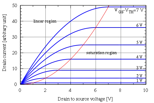
It's all down to little differences when using a 5 volts (Arduino) logic drive level. The SSF1010 will be about twice as good as the IXTP130N15X4 in on-resistance: -

enter image description here

Sometimes you need to look hard.

Andy aka
  • 434,556
  • 28
  • 351
  • 777
  • 1
    Andy knows these Graphs are always "nominal" and your tolerances will vary these results. i.e. from 2 to 4 , if nominal is Vgs(th) = 3V you need at least Vgs=6V but if Vgs(th)=4V, you need 8V – Tony Stewart EE75 Feb 21 '21 at 22:18
  • That's correct but, on average, the on-resistance of the SSF device will be about twice as good as the IXYS device but, there could be situations where 1 device performs very similarly to the other however, if you had to put money on one device to win you'd choose the SSF1010. Nine times out of ten it would be better and maybe 1 in 10 it might be a dead heat. – Andy aka Feb 21 '21 at 22:21
  • 1
    @vangelo If I didn't I'd be leaving a strongly worded comment under your answer LOL. It's up to the OP; he may only have these two devices available and he's probably knowledgeable to know that it might be asking for trouble operating them in the shallow end of the ohmic region. – Andy aka Feb 21 '21 at 22:30
  • 1
    @Andyaka Thanks for the feedback – devnull Feb 21 '21 at 23:57
4

Put yourself a Dickson Charge Pump on that gate and drive the DIO pin with PWM to act as a pseudo A/C drive. Use 100K resistor for the gate discharge.

schematic

simulate this circuit – Schematic created using CircuitLab

EDIT: I put this on a breadboard and got 9.8V on the gate, so I updated the schematic to be more accurate.

Second Edit inspired by comments from vangelo. Arduino Vcc replaced with low pass filter for deriving input voltage.

ScienceGeyser
  • 1,526
  • 3
  • 9
  • 2
    I guess instead of "arduino vcc" you meant to use another DIO, right? – devnull Feb 22 '21 at 00:28
  • 1
    @vangelo Indeed, You do want to turn the thing off I guess, and putting the clocked DIO pin to ground will only take the gate down to Vcc. Thanks for pointing that out, I'll update the schematic. But I'll use a lowpass filter from the PWM pin to get the voltage. – ScienceGeyser Feb 22 '21 at 00:45
  • 2
    I used a duty cycle of about 80% (analogWrite(5, 200);) on the DIO to get 4V on C3 and this gave a nice 8.0V on the gate. – ScienceGeyser Feb 22 '21 at 01:04
3

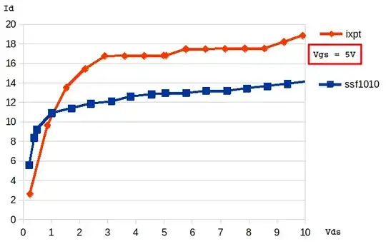
As you can see, it is very difficult to extract data from such low operating points:

enter image description here

enter image description here

But, in agreement with the other answers, you see that one of the mosfets is superior for low currents (also in agreement with your measurement):

enter image description here

If your solenoid can handle the current, you can increase the voltage (but watch the power dissipation in your mosfet).

Besides the Vth, which is the main issue, you probably know these mosfets (~100V ~100A) are not ideal for this application. You may choose one with lower threshold voltage. Lower Vds and Ids can also be found with very low Rds.

devnull
  • 8,447
  • 2
  • 15
  • 38
3

Modify your driver for more gate voltage. The coil can be at any voltage you choose within its power rating.. You might even get away with 5V for Vgs pullup for my R2.

schematic

simulate this circuit – Schematic created using CircuitLab

for Vgs(th) 2 to 4V @ 250 uA , you need > 8V to gaurantee decent RdsOn.

Tony Stewart EE75
  • 1
  • 3
  • 54
  • 182