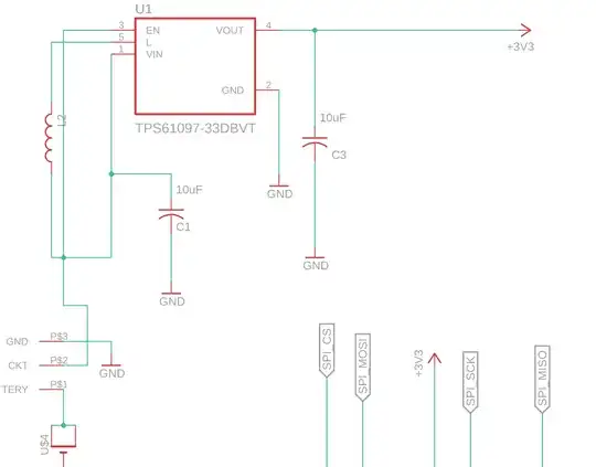
 I ve been trying to get the TPS61097A-33 working to get the promised 3.3V output voltage. I am using two AAA batteries as input and the circuit current draw is 20mA. I am using 4.7uH inductor and 10uF caps at the input and output as indicated by the datasheet...on connecting batteries I get a lower voltage of around 2.5V at the output when the load is connected and around 3 V when no load...Does anyone have any experience with this ?
Asked
Active
Viewed 82 times
0
Nav
- 1
- 1
-
1Schematics please? – Justme Feb 21 '21 at 21:48
-
Schematic mandatory. Ditto a link to the chip. – Andy aka Feb 21 '21 at 21:55
-
DCR, ESR , L and C all matter as well as a soft start – Tony Stewart EE75 Feb 21 '21 at 21:57
-
Hi added schematic and link to chip..thanks – Nav Feb 21 '21 at 21:59
-
Did you substitute parts and change layout. – Tony Stewart EE75 Feb 21 '21 at 22:01
-
yes, not the same parts mentioned in the datasheet but the parts I used are of the same specification...I have used a small 0805 inductor of 4.7uH and same size caps of 10 uF – Nav Feb 21 '21 at 22:05
-
Try measure the input voltage on Vin pin when no load and load also. Are you sure you are not supplying some (hidden) load on board? Btw, the pcb design is terrible, your gnd at output cap is too long. The power traces should be thicker and short, use vias to connect to bottom gnd plane. – Feb 21 '21 at 22:32
-
2Perhaps your parts are not as ideal as shown in App note, also your layout has no resemblance to theirs. When doing these designs , it is a good idea to copy everything ,as the performance is greatly affected. https://i.stack.imgur.com/oyBbR.png rip up and re-try – Tony Stewart EE75 Feb 21 '21 at 22:32
-
I agree with Michal, the layout seem to be either faulty or not showing all details. Ground routed as long traces or not connected at all? If you have a scope it's time to hook it up to the input and output and observe the behaviour. Try doing it with a lab power supply instead of the batteries also. With batteries you have to concider charge level, internal restistance and last but not least bad connectors. – Dejvid_no1 Feb 21 '21 at 22:36
-
2There is no spec for L given or shown on layout .. errors – Tony Stewart EE75 Feb 21 '21 at 22:37
-
@MichalPodmanický Yes, the ground line is long as I couldn't add vias because there is a cr2032 battery on the other side. I checked without load, the input voltage is 3 V from fresh two AAA batteries. I will rectify the PCB design issues but I am not sure that these issues are causing the chip not to boost to anywhere near to 3.3v. – Nav Feb 21 '21 at 22:43
-
What load resistor are you testing it with? – Andy aka Feb 21 '21 at 22:49
-
11) Don't underestimate the design quality, when converter works at light load (discontinues mode) there is too much spikes, i.e. hard to controll. 2)I would focus on inductor size, the bahavior of converter depends too much of this parameter. Try use lower/higher uH inductor to hold 3v3 output at desired loading. – Feb 21 '21 at 23:06
-
1@MichalPodmanický Yes the inductor is what i suspect as well. I have ordered 10uH inductor and will test them this week....thanks – Nav Feb 21 '21 at 23:08
-
Ok, just remember the lower uH inductor can be also the solution in some cases. (Vin, Load values). – Feb 21 '21 at 23:21
-
1Need inductor spec. A common beginner mistake is to use an RF inductor instead of a power inductor. – Mattman944 Feb 21 '21 at 23:42
-
@Mattman944 this is the inductor i am using: https://uk.rs-online.com/web/p/multilayer-surface-mount-inductors/7242734/ – Nav Feb 22 '21 at 00:34
-
That is an awful layout for a boost converter. You need to use much thicker traces for anything which carries any current, *including ground*. You also need to move your input cap C1 right next to the IC and connected with short fat traces. The inductor L2 similarly needs short fat traces to C1 and pin 5. Your output cap C3 has a ground connection which apparently takes such a long and torturous path back to the rest of the boost converter components that we can't even see it in the pic! *You need to use Short, Fat, Traces!* I'm afraid a new inductor is not going to help you here... – brhans Feb 22 '21 at 04:25
