6

I want to make a counter that can count the time between pulses in nanoseconds. The counter starts to count when a pulse enters a pin (at the start of the pulse) then stops when a second pulse comes. Then the timer sends a signal to either a display or LED and starts the counting again.

Diagram showing example image of pulses


The time between each pulse is anything from 100 ns to 1 s and the pulse width is 100 ns to 1 µs. The counter needs to be as cheap as possible and does not need to give me a 100 % accurate time. For example, if the time is 100 ns and the counter says its 200 ns it is acceptable (basically ±100 ns).

  • Resolution: There is no need for it to read in 0.1 ns but rather 10 ns steps.
  • Display: Either a simple LCD, CRT or anything really.
  • Noise: The pulse will be from 0.5 V to something higher.
Null
  • 7,448
  • 17
  • 36
  • 48
20Ola02
  • 87
  • 1
  • 5
  • So you need some kind of counter that will run at at least 1GHz. Have you looked for anything like that? – Elliot Alderson Feb 20 '21 at 18:12
  • You'll need a time of flight IC, ns is too hard to DIY – Voltage Spike Feb 20 '21 at 18:18
  • 2
    What is the time between pulses? If it is log enough vernier techniques can be used to avoid the necessity for clocking at very high frequencies. – Kevin White Feb 20 '21 at 18:56
  • The time between is anything from 100ns-1s and the pulsewidth is from 100ns to 1us. – 20Ola02 Feb 20 '21 at 19:06
  • @20Ola02 uff, tough one! Is this happening periodically, or is every measured time going to be different? – Marcus Müller Feb 20 '21 at 19:21
  • @MarcusMüller the times will be different each time but the pulsewidth of the signal is controlled and is from 100ns to 1us. – 20Ola02 Feb 20 '21 at 19:22
  • 8
    Counters like this cost over $500 to buy with 1GHz stable clocks and PECL counter chips cascaded with 74ALC variable decade clock dividers for X digits of resolution over 7 decades of time interval . Define your resolution (digits) , sensitivity and accuracy specs **first** then decide/define what you can buy. – Tony Stewart EE75 Feb 20 '21 at 19:32
  • What sensitivity and display? How much noise? Just a 1-shot measurement? – Tony Stewart EE75 Feb 20 '21 at 19:38
  • 5
    SInce this is a 1-shot measurement, do you really need 10 ns resolution for a 1 second interval? Your specs are insufficient for any suggestions to be valid. Can you anticipate the duration ahead of time to vary the clock resolution? Otherwise you need a 8 digit display – Tony Stewart EE75 Feb 20 '21 at 20:11
  • The cheap NI USB DAQ boards all do 125 ns counters at a minimum. – user1850479 Feb 20 '21 at 20:27
  • Your question ought to be , How do Time Interval counters work? Because until you know how to define every specification and tolerance for every condition , you can't design one – Tony Stewart EE75 Feb 20 '21 at 20:49
  • 1
    Do you know about the picPET? Gives 100 ns (or even 50 ns) accuracy for $5. Search the web for it. – tomnexus Feb 21 '21 at 05:07
  • 1
    @tomnxus mentioned PICpet here and many elsewheres http://www.leapsecond.com/pic/picpet.htm – Russell McMahon Feb 21 '21 at 07:06
  • 12
    Aha, you've relaxed the requirements by two orders of magnitude... That of course basically invalidates all answers you've already gotten. – Marcus Müller Feb 21 '21 at 11:34
  • 2
    There's still a contradiction in your requirements. First you say ±100 ns is acceptable, but then you mention "10 ns steps" under Resolution. That's again a huge difference. – TooTea Feb 21 '21 at 22:07
  • 1
    @TooTea There's a difference between accuracy (which is what I'd assume the ±100 ns requirement means) and precision (which is related to resolution). So I don't think this is a contradiction, strictly speaking. – Hearth Feb 23 '21 at 14:34
  • A Stanford Research SR620 has 25ps single shot resolution. All depends on your real needs and budget to get there. – Jon Custer Feb 23 '21 at 16:41

7 Answers7

27

You've changed the requirements by a lot! Measuring something in nanoseconds is hard. Measuring something with a +-100 ns accuracy really isn't. A 10 MHz counter works perfectly fine for that, do 20 MHz if you want to be sure.

Any modern 32 bit microcontroller (read: 2€ investment...) has timer/capture units that can do that for you.

You've went from a problem that requires own hardware design to something that even the cheapest STM32 eval board can do out of the box: That's an excellent illustration of the importance of requirements engineering.

Marcus Müller
  • 88,280
  • 5
  • 131
  • 237
16

Luxury option:

Time to digital converter chip, available from several manufacturers. Accuracy: picoseconds.

AS6500 TDC7200

Easy option:

Microcontroller timer in capture mode to measure pulse width, or time between two pulses. Pretty much any microcontroller will do the job, but accuracy will be at best one clock cycle, so you must choose a microcontroller with suitable clock frequency. And you must also check the timer clock frequency, which is not always the same as the CPU clock frequency. If you want 10ns accuracy that's 100MHz, so there are a lot of options, STM32, LPC, etc. If you want a LCD, just get a module with one on it.

ESP32 is an example of why you should check carefully: the CPU runs at 240 MHz but the timers run at 80MHz.

Next, check the microcontroller datasheet and check if the timer can measure the delay between two pulse edges. If it cannot, then you can use two timers running on the same internal counter to capture the start pulse and the stop pulse counter values, and just substract.

Since you're interested in edges, make sure it can be triggered on the leading edge.

the pulse will be from 0.5V to something higher.

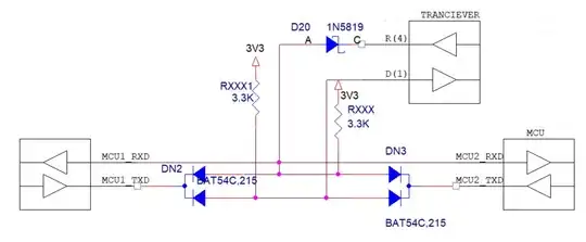
0.5V is too low for a CMOS logic input so you will need a fast comparator to set a suitable threshold, search the category on mouser, digikey etc. It's important to select a comparator with a response time that is low enough. If your minimum pulse width is 100ns, then a <50ns comparator should be adequate. You can also use a highspeed opamp to amplify the signal, but in any case, a CMOS 3V3 logic input will not work directly with a 0.5V signal.
bobflux
  • 70,433
  • 3
  • 83
  • 203
  • 2
    use an analog integrator to measure the time between counter clock pulses. The measured pulse stops the integrator and counter. Measure the voltage on the integrator with an adc and along with the count value gives you a high resolution timing measurement. Eg: a 10 bit adc and 10MHz counter will achieve ~1ns resolution. 50MHz count would give 200ps resolution and so on. – Kartman Feb 20 '21 at 23:49
  • @jms nice find! So the high resolution also applies to capture mode? – bobflux Feb 21 '21 at 08:43
  • Sorry, I remembered wrong - The input capture is limited to the input frequency of the high resolution timer, which maxes out at [144MHz (on the STM32F334)](https://www.st.com/resource/en/reference_manual/dm00093941-stm32f334xx-advanced-armbased-32bit-mcus-stmicroelectronics.pdf) – jms Feb 21 '21 at 13:30
  • Still good enough for 7ns accuracy, excellent deal at 4€/piece qty one and probably available on cheap ST dev board too, that would be an excellent choice for OP! – bobflux Feb 21 '21 at 14:31
  • @jms actually, one could use the HRTIMER to generate a multiphase clock, say 6 outputs with each having its edge delayed by 1/6 period, or 1.15 ns. Using these as data inputs for a bunch of fast flops like 74LVC, with the pulse to be detected as clock input, then looking at the flop outputs, one can tell the pulse edge timing relative to each and divide the period in slices for up to 1ns accuracy, not bad for a 4€ micro and a bunch of 20c flops... – bobflux Feb 21 '21 at 14:34
  • ST advertises 184PS in the HRTIMER in the G4 series, which is a successor to F3 – jaskij Feb 21 '21 at 19:01
9

Your cheapest solution is going to be determined by the cost of your time , components and circuit board with debug time.

In this case your best solution is a used 100 MHz counter off EBAY for $150

https://www.ebay.ca/itm/AGILENT-HP-5316B-HIGH-PERFORMANCE-FREQUENCY-COUNTER-100-MHz-LOOK-REF-330G/193032320482?hash=item2cf19f75e2:g:O8UAAOSws3ldSDHf

Tony Stewart EE75
  • 1
  • 3
  • 54
  • 182
9

(basically +/- 100ns).

Well then, a cheap 8-bit microncontroller like ATTINY2313 can be clocked at 20Mhz, then you can just use its timers in input capture mode and that will get you +/- 25ns precision at each end of the pulse for over-all +/- 50ns precision (modulo clock jitter and innacuracy so use a good crystal for the clock) 75ns accuracy should be possible.

8

I think the most realistic approach here is probably still a bit tricky:

First of all, you'll have to realize that your signal has a pretty high bandwidth, assuming that the rise time of your pulses needs to be pretty steep to even get the required timing accuracy (e.g. if your rise time is 40 ns, then in 1 ns of an edge not that much voltage difference happens, and the tiniest bit of noise and component temperature variation can skew your measurement beyond your target accuracy).

That means your board design needs to be wideband-aware, which basically means you need to design this as a high-speed logic or RF board, with appropriate buffers/amplifiers, matched traces, matched in- and outputs and so on.

Assuming you get the analog side sorted out, most logic is still too slow to count that fast, and most discrete logic is also too small to count up to a billion nanoseconds!

So, what I think this will boil down to is "abusing" fast inputs on an FPGA to reduce the rate at which you can work.

Two approaches:

  1. Use an FPGA with a high-speed SERDES. The ECP5 series by lattice might work. Get one with a 2.5 Gb/s or higher SERDES, and use it to sample your signal at a Gigabit per second, convert it to to 10bit units, so that your counting can happen at a much easier 100 MHz, and do the counting in-FPGA. For the 10 bit symbol where the signal changes, you just need to find the first changed bit in these 10 to figure out things with nanosecond precision.
  2. Use an FPGA with wide parallel buses (say, N bit wide) where you can program artificially added skew between different inputs in N steps up to N-1 nanoseconds. Feed (matched length!) the same signal to all N inputs, and sample every N nanoseconds.

I think the first alternative is easier. In both cases, you'd buy an FPGA evaluation board to get across the initial hardware design hurdle.

Marcus Müller
  • 88,280
  • 5
  • 131
  • 237
  • To extent your list of FPGA solutions: 1 ns precision can easily be reached with a clocked sampling of the signal, using 2 or 4 clocks shifted using a PLL. A cheap 5€ MachXO3 FPGA or a 25€ evaluation board will do. – asdfex Feb 21 '21 at 11:17
  • @asdfex that's an interleaved ADC you're building there :D Never worked with the Mach serieses, do they have sufficiently many PLLs that you can also relate in phase built-in or is that something you'd need to construct externally? – Marcus Müller Feb 21 '21 at 11:32
  • @asdfex I just read the edit that OP went through... we're now from "count nanoseconds" to "+- 100 ns accuracy". Of course, implementing a 10 or even 20 MHz counter can be done with about anything, including bog-normal microcontrollers. – Marcus Müller Feb 21 '21 at 11:39
  • 1
    MachXO3 has 1 or 2 PLL per device, but each PLL has 4 outputs that can be shifted with respect to each other. Like ECP5. 100 ns, 10ns or even 5ns are another story.... – asdfex Feb 21 '21 at 11:40
5

Counting pulses with 1ns precision is a tall order. That rate rules out all the commonly used logic families like 74XX, CD4XXX, etc. Even the "high speed" varieties are nowhere near fast enough.

That leaves you with ECL (Emitter Coupled Logic) as the next step up. These are fairly expensive and use a lot of power but when that's what you need, you use them.

For example there is the ON Semiconductor MC100EP016AFAG which is an ECL 8-bit up/down counter. It's datasheet is here:

ON Semiconductor ECL 8-bit Counter

You can see from the timing that is can be clocked at 1.3GHz at 70C:

MC100EP016AFAG Timing

Of course you don't just drop one of these into a breadboard and expect it to work at this speed. You will need to follow RF design rules very carefully.

Good luck as this will certainly be a challenging project but I am sure you'll learn a lot in the process.

jwh20
  • 7,812
  • 1
  • 16
  • 27
4

Since you imply that 10 ns resolution is acceptable, a 50 OR 100 MHz timer can be built with either 10K or 100K ECL, or Schottky TTL (74Sxx or 74ASxx).

You will need an accurate 50-100 MHz oscillator to clock the counters, and this is not a simple thing to design.

Note that at your frequencies, the display will be updating far more rapidly that the eye can perceive.

AnalogKid
  • 16,865
  • 1
  • 13
  • 25