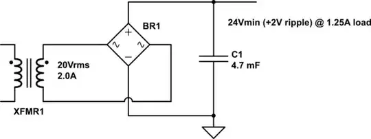
This is a linear power supply schematic. I understand 90% of the schematic but that constant current sink is giving me trouble. Can someone explain the purpose of it?
Asked
Active
Viewed 139 times
0
Faraz Ahmed
- 49
- 5
-
What problem, can you ask a more specific question? – Marko Buršič Feb 12 '21 at 19:03
-
sorry mate! updated the question. – Faraz Ahmed Feb 12 '21 at 19:09
-
1Exactly what it says. Acts like a dummy load and sink 20mA at all time. – Adam Lawrence Feb 12 '21 at 19:09
-
no no I get that bit but why do I need this? – Faraz Ahmed Feb 12 '21 at 19:11
-
3You'll likely discover that **without a 20mA** load, current through that big TIP142 may try to reverse when you provide no external load. – glen_geek Feb 12 '21 at 19:26
1 Answers
1
The purpose is to have a correct regulation at near zero volt output. But in my opinion the circuit is wrong, as it should pull the current below zero voltage and the power BJT transistor should just compensate that leak.
EDIT:
Perhaps you will find some information in this answer, how this simple/non-precise current sink works. But your circuit can't do the function it was planned for. Without a current sink, you won't be able to control low voltages. If introduced, it has to be supplied also with negative voltage, so that it keeps the main BJT always conducting a "little bit".
EDIT 2:
After user Bruce Abbott comment, I see that original schematics is OK, I didn't see the detail. So forget about my "correction"
Marko Buršič
- 23,562
- 2
- 20
- 33
-
So it's just there to make the circuit stable when regulating low voltages....right? and can you elaborate your solution more please? – Faraz Ahmed Feb 12 '21 at 19:16
-
GND is connected to the **positive** output terminal. The constant current sink is required to pull the negative terminal _up_, so it must be connected to there. – Bruce Abbott Feb 12 '21 at 19:57
