1

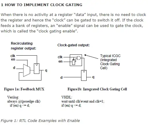
I'm studying to implement a Clock Gating in RTL. So I've followed as the below

https://www.design-reuse.com/articles/23701/power-analysis-clock-gating-rtl.html

enter image description here

always @(posedge clk)
begin

    if (enable_in)
        gclk <= clk;

end

But Problem is that I encounter an Error Message when I synthesis above code.

TOP.v:55: Clock clk used as data. (ELAB-305)

It does not makes sense Because this is just gating signal not a data. If I wrong, Could you please guide me?

How to implement Clock Gating STYLE code into RTL ?

Full Code :

module  omsp_clock_gate (

// OUTPUTs
    gclk,                      // Gated clock

// INPUTs
    clk,                       // Clock
    enable,                    // Clock enable
    scan_enable                // Scan enable (active during scan shifting)
);

// OUTPUTs
//=========
    output reg        gclk;           // Gated clock

// INPUTs
//=========
    input          clk;            // Clock
    input          enable;         // Clock enable
    input          scan_enable;    // Scan enable (active during scan shifting)

    wire    enable_in =   (enable | scan_enable);

    always @(posedge clk)
    begin

        if (enable_in)
            gclk <= clk;

    end

endmodule // omsp_clock_gate


module TOP(Clk, Reset, Crnt_Instrn, Zro_Flag, Carry_Flag, Neg_Flag, Return_Addr, Current_State, PC);
        input                   Clk;
        input                   Reset;
        input   [31:0]  Crnt_Instrn;            // Current Executing Inst
        input           Zro_Flag, Carry_Flag, Neg_Flag; // Flags from ALU or Stack
        input   [7:0]   Return_Addr;
        output  [2:0]   Current_State;          // CurrentState from Control FSM 
        output  [7:0]   PC;     // Program Count

        wire                    Incrmnt_PC, Ld_Brnch_Addr, Ld_Rtn_Addr;
        wire    [2:0]   CurrentState;

        
          omsp_clock_gate u_omsp_clock_gate (
    // OUTPUTs
        .gclk   (   gclk        ),                      // Gated clock
    
    // INPUTs
        .clk    (   Clk     ),                       // Clock
        .enable (   Neg_Flag        ),                    // Clock enable
        .scan_enable    (   1'b0)                // Scan enable (active during scan shifting)
);


        FSM     I_FSM (
                .Clk(Clk),
                .Reset(Reset),
                .CurrentState(CurrentState)
        );


        DECODE  I_DECODE (
                .Zro_Flag(Zro_Flag),
                .Carry_Flag(Carry_Flag),
                .Neg_Flag(Neg_Flag),
                .CurrentState(CurrentState),
                .Crnt_Instrn(Crnt_Instrn),
                .Incrmnt_PC(Incrmnt_PC),
                .Ld_Brnch_Addr(Ld_Brnch_Addr),
                .Ld_Rtn_Addr(Ld_Rtn_Addr)
        );


        COUNT   I_COUNT (
                .Reset(Reset),
                .Clk(Clk),
                .Incrmnt_PC(Incrmnt_PC),
                .Ld_Brnch_Addr(Ld_Brnch_Addr),
                .Ld_Rtn_Addr(Ld_Rtn_Addr),
                .Imm_Addr(Crnt_Instrn[7:0]),
                .Return_Addr(Return_Addr),
                .PC(PC)
        );


        assign  Current_State   = CurrentState;

endmodule
Shashank V M
  • 2,279
  • 13
  • 47
Carter
  • 581
  • 2
  • 6
  • 23
  • 1
    If this is for FPGAs, SCRAP THIS APPROACH. You can't have combinational paths on clock routes. Very bad practice. Instead of that, make use of clock enable pins in flip flops instead to save power at the cost of performance. – Mitu Raj Feb 13 '21 at 11:51

1 Answers1

2

You are trying to sample the clock signal on the rising edge of itself. This violates Nyquist criterion since you are sampling the clock signal at its frequency and not twice its frequency.

As the name implies, clock gating should use a gate, an AND gate.

You need to have the gating signal toggle on the inactive edge of the clock to avoid glitches. You can either use a latch or flip-flop to ensure the clock gating signal only transitions on the inactive edge of the clock.

For latch:

always_latch 
  if (~clk)
    enable_latch <= enable_in;

assign g_clk = clk & enable_latch;

For flip-flop:

always_ff @(negedge clk)
  enable_flop <= enable_in;

assign g_clk = clk & enable_flop;

Also a point to be mentioned: if you are using clock gating in your design, you should avoid driving signals with blocking assignments on clock edges in the testbench as this could lead to race conditions.

Further reading: How to use clock gating in RTL?

Shashank V M
  • 2,279
  • 13
  • 47
  • I confused that here is no register, How does tool recognize this for clock gating "assign g_clk = enable_in & clk;"? – Carter Feb 15 '21 at 07:13
  • @Carter, this is a different approach, the enable input for register is a different approach. Usually, people refer to clock-gating for the and gate having 2 inputs: clock and enable. – Shashank V M Feb 15 '21 at 07:36
  • Yes I know usually people use clock and enable approach which is gated data by gating clock in register. In register approach, I never seen the clock itself gating approach. so basically this is my question from it. – Carter Feb 15 '21 at 08:50
  • @Carter, the other approach is just a flip-flop with an enable. – Shashank V M Feb 15 '21 at 09:05
  • About https://github.com/YosysHQ/yosys-bigsim/blob/master/openmsp430/rtl/omsp_clock_gate.v this approach doesn't used a register for clock gating. and this is the what I 'm saying that clock itself gating – Carter Feb 15 '21 at 11:16
  • @Carter, I had not included in the code previously, but I had mentioned it in my answer. I have included it in the code now. See my edit – Shashank V M Feb 15 '21 at 11:53
  • Let us [continue this discussion in chat](https://chat.stackexchange.com/rooms/119769/discussion-between-shashank-v-m-and-carter). – Shashank V M Feb 15 '21 at 11:56