1

Here I have a Colpitts oscillator:

enter image description here

The feedback fraction is C1/C2.

However during an LTSpice simulation if we set C1 = C2 the oscillation is not underdamped. How is this possible since we will get a feedback fraction of 1 and the voltage gain of a BJT is always less than 1 so the oscillation must die out?

JRE
  • 67,678
  • 8
  • 104
  • 179
Clone Wars
  • 21
  • 5

2 Answers2

2

Who told you that the "feedback fraction" would be C1/C2? Please note that any oscillator needs a frequency-dependent feedback path that allows oscillation at one single frequency only. Therefore, the oscillation criterion - UNITY LOOP GAIN - must be fulfilled at this single frequency only.

In the shown example, the feedback path is a thrird-order lowpass (classical ladder topology), which provides a -180deg phase shift at one frequency only. Together with the phase inversion of the transistor stage (with sufficient gain between base and emitter) this configuration meets the mentioned oscillation criterion (Barkhausen).

The 3rd-order lowpass is formed by the grounderd R4-C1 combination (1st-order lowpass) and a grounded second-order lowpass (L1-C2) which is connected at the node between R4 and C1. This assumes that Cout is a (large) coupling capacitor only and that the output resistance of the transistor is mainly determined by R4 only.
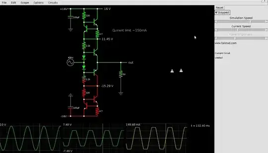
LvW
  • 24,857
  • 2
  • 23
  • 52
  • The feedback fraction through C1, C2 and L has a magnitude of C1/C2 - maybe you are thinking of the common collector circuit that has the feedback fraction of (C1+C2)/C2? – Andy aka Jan 31 '21 at 16:09
  • 1
    Andy aka, I know what you mean - and you are right when we neglect the load resistance at the base node (ideal lowpass). However, in most cases, we have to take into account R1||R2||hie. And - I must admit, I did not mention this load in my answer. – LvW Jan 31 '21 at 16:54
1

during an LTSpice simulation if we set C1 = C2 the oscillation is not underdamped. How is this possible since we will get a feedback fraction of 1 and the voltage gain of a BJT is always less than 1 so the oscillation must die out?

Your amplifier (yes it's a voltage amplifier) is a common emitter configuration and it will have bags of voltage gain.

If you were using a common collector transistor then voltage gain would be slightly below 1 but the \$\pi\$ network would introduce voltage gain and permit circuit oscillation.

Here are the three main types of BJT Colpitts oscillators: -

enter image description here

Picture from here and yours is the middle one. Related questions: -

The above answer contains the proof that the gain of the \$\pi\$ filter is -C1/C2

Andy aka
  • 434,556
  • 28
  • 351
  • 777
  • which is the feedback fraction of the 3rd colpitt oscillator(from left to right)?Just asking. – Clone Wars Feb 05 '21 at 18:19
  • @CloneWars it’s (C1 + C2) / C1 for the common collector version I.e. the filter produces voltage gain. – Andy aka Feb 05 '21 at 18:35
  • Ah okay thanks. LwV says it is (C1+C2)/C2. They are 2 contradictory posts.And you say in a past comment that is C1+C2/C2. So which one is it? – Clone Wars Feb 05 '21 at 18:41
  • It all depends on which capacitor you call C1 and which you call C2. In the circuit in my answer above, the denominator is C1 but if they swapped it would be C2. If you look in [this post I made](https://electronics.stackexchange.com/questions/355018/colpitts-oscillators-capacitors/355062#355062) you'll see that I use C2 in the denominator because C1 is the capacitor that is grounded @CloneWars – Andy aka Feb 05 '21 at 19:50