2

I have searched the internet on how to get positive and negative voltage from the same power supply and I found the attached circuit.

When I measure between the points A and B, I get +5V. When I measured between C and B, I get -0.5V.

What is the reason or what is the error in this circuit?

enter image description here

JRE
  • 67,678
  • 8
  • 104
  • 179
user255471
  • 51
  • 1
  • 8
  • I don't believe they're meant to operate in a stacked arrangement like that. They need a little bit more than 5V to output 5V is another problem. How do you feel about switching regulators? – K H Jan 31 '21 at 09:55
  • Oh and what/how big is your load? – K H Jan 31 '21 at 09:57
  • My load is op amp – user255471 Jan 31 '21 at 09:58
  • 1
    The input to that circuit is 10v DC – user255471 Jan 31 '21 at 09:59
  • How many mA? The problem is you're trying to stack them towards eachother instead of away from eachother, and you're also doing that wrong. But if you did it right it would still cause problems. To get regulated +5/-5 out of 78/7905 you need to use a center tap and slightly more than 10v. Isolated output switching regulators would do the trick for you though or one inverting and one non inverting converter. – K H Jan 31 '21 at 10:03
  • You can think of the ground pin on a linear regulator as essentially just a reference voltage. Taking that into account, you can see that your virtual ground is essentially floating. – Drew Sep 23 '22 at 01:39
  • Put a 100 ohm load resistor on one of those outputs and try to determine the current loop for it. – Drew Sep 23 '22 at 01:40
  • Related: https://electronics.stackexchange.com/questions/331371/problem-in-using-a-buffered-virtual-ground-as-opamp-split-supply – Jens Nov 02 '22 at 23:40

5 Answers5

3

You are using positive and negative linear regulators to obtain +/- 5 volts from a single ended 10 volt input supply. That will not happen. You'll need probably at least 16 volts applied to the input for this to happen.

Then, when you have enough supply voltage, the 0 volt (mid-rail) output from the regulators won't be able to cope with anything more than maybe 5 to 10 mA load imbalance on the regulated outputs and one of the outputs (either + or -) will collapse.

You are also using ridiculously low values of input and output capacitors.

I'd consider using an inverting configurated buck converter to generate the negative supply rail like this: -

enter image description here

Picture from this post.

There is also this device (picture from the device data sheet): -
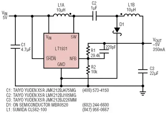
enter image description here

Andy aka
  • 434,556
  • 28
  • 351
  • 777
  • Dear sir..i have tried to input 15v DC. but i still get +5v and -.05 v...what is the problem sir...? – user255471 Jan 31 '21 at 10:23
  • Try adding two 1 kohm resistors to make a mid-rail potential divider to point B from the incoming supply. But, it's never going to be suitable for anything much however, if you want to pursue this to the bitter end then that's fine. – Andy aka Jan 31 '21 at 10:31
  • Ok,i will try..But is not there any other stable and reliabe method to get +/- volt from one power supply? My great pleasure..... – user255471 Jan 31 '21 at 10:34
  • Yes, use an inverting buck regulator to generate a proper negative power rail. – Andy aka Jan 31 '21 at 10:36
  • Thank you sir...could you mention me a certain buck regulator to work with. Also could you mention me a link on internet to read a lot about this topic...thanks in advance... – user255471 Jan 31 '21 at 10:51
  • I don't have links to hand because I don't need to read them. LM2596 springs to mind. I'll add it to my answer. – Andy aka Jan 31 '21 at 10:54
  • Thank you very much sir..my great pleasure..... – user255471 Jan 31 '21 at 10:57
  • @user255471 The wikipedia articles on DC-DC voltage converters are great. It has all the types, how they work, what they're good for and schematics. – K H Jan 31 '21 at 11:16
  • Thank you my sir...Great pleasures – user255471 Jan 31 '21 at 11:35
  • Great pleasures to you too lol. – K H Jan 31 '21 at 12:08
1

How to get +/-5v W/ 7805/7905

schematic

simulate this circuit – Schematic created using CircuitLab

You can see that with the intended wiring, 7805 chops the positive voltage down to 5V and 7905 chops the negative down to five volts, but it needs negative voltage to start with, so you need a split source with a ground rail in the middle to use them this way.

K H
  • 4,023
  • 1
  • 11
  • 24
  • The [7805](https://www.st.com/resource/en/datasheet/l78.pdf) needs at least 7 volts to produce 5V. The [7905](https://www.ti.com/lit/gpn/lm79) needs below -6.1V to put out -5V. – JRE Jan 31 '21 at 12:22
  • @JRE Ooopsie doodle let me fix that – K H Jan 31 '21 at 12:23
  • But this sir is done using two power supplies,not one power supply.. – user255471 Jan 31 '21 at 12:41
  • That is my point, although it could be one power supply with split output. You could run your supply through an inverter to get + and - output, but really you'd be better off with a switching regulator. I just posted this to show you what went wrong and how it has to be to work. – K H Jan 31 '21 at 12:43
  • Your need a virtual ground for this to work – Voltage Spike Nov 02 '22 at 23:29
0

Number 1: The 7905 is hooked up incorrectly. Check the pin connections.
Number 2: For this to work one would have to have a negative and positive voltage input.
Number 3: the input capacitor values are fine when batteries are used for input but larger output caps are needed, something in the order of 10 μF or so.

ocrdu
  • 8,705
  • 21
  • 30
  • 42
0

What's Wrong? Well the 7905 pin1 is GND pin2 input and pin3 output. The 7805 pin 1 is input pin2 GND and pin3 Output Don't know where the other person got 10uf caps from If you check the datasheet it recommends 2.2uf on the input and 0.1uf on the output side for a 7905 and 330nf and 0.1uf for a 7805. You can absolutely use 7805 and 7905 regulators stacked in that way it does indeed show that in the datasheet. However in the data sheet it also shows a pair of 1n4002 diodes between the output rails. As others have already said to generate a dual rail supply you need to start with a center tapped transformer and full wave bridge rectifier and a pair of smoothing caps 2,200uf or 4,700uf rated about 10V higher than the peak rectified voltage. If you are trying to power from a single rail DC supply then you need to be around 6V higher than the combined output of both regulators (3v each) use 2off 10K 10w resistors as a potential divider between positive and negative to give youself an 0V line at the point the 2 resistors join

0

XY problem?

At any rate, neither regulator has enough overhead voltage to achieve a stable output. You’d need at least 16V for that to work.

If your goal is to create a virtual ground that is mid-way between 0 and 10V, there’s a better way: a virtual ground circuit using a buffered op-amp.

Here’s a whole collection of approaches to doing just that: How to increase the output current of a dual supply (virtual ground) circuit

hacktastical
  • 49,832
  • 2
  • 47
  • 138