4

In a recent lecture in my AC Circuits course, the professor put this slide up and hastily explained the Universal Op-Amp. Since I already struggle with circuits, let alone operational amplifiers, I did not understand his explanation very well. What is Ag, Rg, or Ai?

Could someone with extensive knowledge on Op-Amps break this slide down for me so I can have something to complement the lecture I received?

Also, what is the purpose of these types of Op-Amps?

They look very similar to summing Op-Amps. Also where it says, "This formula subsumes all previous configurations," the professor had just gone over five standard Op-Amp Configurations prior to this one. enter image description here

Circuit fantasist
  • 13,593
  • 1
  • 17
  • 48
Jared M
  • 83
  • 6
  • At start try to read this https://electronics.stackexchange.com/questions/441184/op-amp-virtual-ground-principle-and-other-doubts/441207#441207 – G36 Jan 22 '21 at 20:55
  • 2
    You really should talk to the instructor about this. If you do that they will almost certainly emphasize the important concepts that you might see later on a quiz. It's a sign of maturity and professionalism to ask for help and clarification when you need it. – Elliot Alderson Jan 22 '21 at 20:55
  • 1
    There is nothing universal about it. Any ideal opamp negative feedback configuration formula can be derived from two basic assumptions: 1) No current is going into opamp inputs. 2) The voltage on both inputs is equal. From here you can easily derive anything else (of course you need the regular basic circuit analysis techniques as well). – Eugene Sh. Jan 22 '21 at 20:55

6 Answers6

5

schematic

simulate this circuit – Schematic created using CircuitLab

Figure 1. The universal op-amp and variations "with bits left out".

What is Ag, Rg, or Ai?

This has been addressed in some of the other answers.

Also, what is the purpose of these types of Op-Amps?

There's nothing special about the op-amps. It's the way they're used that's special - although there's nothing special about these configurations these days.

They look very similar to summing Op-Amps.

The op-amp is the part signified by the triangular symbol. The layout of the inputs and feedback make it into a certain type of amplifier.

Also where it says, "This formula subsumes all previous configurations," the professor had just gone over five standard Op-Amp Configurations prior to this one.

And now s/he's telling you that this one configuration includes all the others. By tying certain inputs to ground or leaving them floating you can create any of the other five configurations.

Texas Instruments make a Universal Operational Amplifier Evaluation Module which allows easy creation of all of these configurations as well as some filter circuits while using surface-mount versions of their op-amps.

Transistor
  • 168,990
  • 12
  • 186
  • 385
  • Thank you for the response, I've tried to do research but came up short which is why I went to Stack Exchange. I will look into what you have said. – Jared M Jan 22 '21 at 22:59
3

in a recent lecture in my AC Circuits course, the professor put this slide up and hastily explained the Universal Op-Amp. Since I already struggle with circuits, let alone operational amplifiers, I did not understand his explanation very well.

I think it's his pet circuit configuration. If I've ever seen that presented, I haven't found it useful to remember -- and I do design op-amp circuits from time to time.

What is Ag, Rg, or Ai?

I'm not going to justify \$A_g\$. It's sorta-kinda the gain from the ground terminal -- but weirdly.

\$R_g = R5\$. That's not well explained.

\$A_i\$ is the gain associated with the input connected to \$R_i\$

Could someone with extensive knowledge on Op-Amps break this slide down for me so I can have something to complement the lecture I received?

Well, first, learn it to get through the class. To analyze it, you should just do the good old fashioned trick of calculating \$V_-\$ as a function of all the inverting input voltages (call them \$V_i\$) and \$V_{out}\$, then calculate \$V_+\$ as a function of all the non-inverting voltages. Then set \$V_- = V_+\$, which should let you calculate \$V_{out}\$ as a function of all that.

Also, what is the purpose of these types of Op-Amps? They look very similar to summing Op-Amps. Also where it says, "This formula subsumes all previous configurations,"

Cynically? To make the prof feel like he's discovered something profound.

Presumably you can take every configuration he's shown you so far and fit them into that model. This assumes that he's shown you inverting, non-inverting, differential, etc.

TimWescott
  • 44,867
  • 1
  • 41
  • 104
  • Thank you for the response. I will look into what you have said. I have tried to get help through the professor but this online format has been a disaster and he's not very good at teaching in the first place. – Jared M Jan 22 '21 at 23:02
3

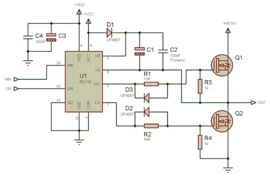
The ideal op-amp is a device that

  • Draws no input current
  • Tries to do whatever is needed at the output to force its two inputs to the same voltage. If there is negative feedback, and the output doesn't hit either supply rail, it will succeed, this is called operating linearly.1

That universal diagram you have is intended to cover most op-amp applications. What you do is delete the components you don't need.

The first thing is to look at Rf. As the amplifier input takes no current, if an input current flows through (say) R1, then 100% of that current has to flow through Rf.

The first configuration then is to use only R1 and Rf, to form an inverting amplifier, if the +ve input is taken to ground. The gain A = Rf/R1.

As you point out, when you add R2 and R3, you get a summing amplifier.

With only marginally trickier mathematics, if you ground R1 (make V1=0), apply the input voltage to R4 and lose R5, you get a non-inverting amplifier, with gain A = R1/(R1+Rf). Work through why this is so yourself.

With suitable choice of input terminals and resistor ratios, you can make a differential amplifier. Replacing resistors with capacitors can give you an integrator or differentiator. Don't attempt these until you understand the basic inverting and non-inverting configurations.

1 Sometimes it hits the rails, and doesn't operate linearly. This happens in real life, good simulators, and also in more advanced questions about op-amps.
Neil_UK
  • 158,152
  • 3
  • 173
  • 387
2

Essence. This professor's creature can be called "universal summing-subtracting op-amp circuit" (not "universal op-amp" since the op-amp is just one of the circuit components). It reminds me of the distant past when analog computers tried to compete with digital ones... but soon lost that battle (analog computers consisted of building blocks and this was one main block).

Structure. The curcuit consists of two passive resistor summing circuits and an op-amp:

  • The upper 4-input summer consists of the four resistors R1, R2, R3 and Rf. The first three are connected to the external input voltage sources V1, V2 and V3; the "feedback" resistor Rf is connected to an internal "input" voltage source - the op-amp output Vout. The output of the summing circuit is connected to the op-amp inverting input.

  • The lower 2-input summer consists of the two resistors R4 and R5. The first is connected to the external input voltage source V4; the second is connected to the internal "ground voltage source" with zero input voltage. The output of this summing circuit (or simply, voltage divider) is connected to the op-amp non-inverting input.

Operation. Since the output of the upper summer is connected to the inverting input, the sum of V1, V2 and V3 appears negative at the op-amp output. Since the output of the lower summer is connected to the non-inverting input, the sum of V4 and Vground (0) appears positive at the op-amp output.

The role of the internal "input" Vout is to neutralize the upper three input voltages V1, V2 and V3. As a result, a virtual ground appears at the inverting input (indeed, it is shifted" by the lower input voltage V4)... and the upper voltage sources are separated from each other.

Calculation. The relation between the voltages can be found by applying the superposition principle.

Properties. Because of the resistors forming voltage dividers, this is a summing circuit with weighted inputs.


You can find more interesting and original considerations about this circuit in the related Wikibooks story; they will help you to figure out the basic ideas behind it.

Finally, I have a request to OP - if possible, to connect me with their professor... I want to exchange some valuable thoughts on how to explain circuits to curious students...

Circuit fantasist
  • 13,593
  • 1
  • 17
  • 48
  • I am technically not a "beginner," my professor would probably argue since I am a junior in computer engineering. However, I have yet to have a circuits professor who doesn't run through important concepts haphazardly. Since I have always struggled understanding circuits, I have always been in a bad spot. This professor struggles with English too, so I imagine he understands what he is teaching but the language barrier is there. Thank you for your insight. – Jared M Jan 23 '21 at 02:25
  • 1
    @Jared M, I perfectly understand you since I have been explaining circuit ideas since the middle 80s to such IT students that are interested in software and not so much in circuits. I try to make them think and not just learn so our classes resemble more brainstorming sessions than conventional classes. I share them on web to inspire curious young people. Look at my [Wikibooks teacher's story](https://en.wikibooks.org/wiki/Circuit_Idea/Joining_Students_of_TU_Sofia) and the [related circuit story](https://en.wikibooks.org/wiki/Circuit_Idea/Walking_along_the_Resistive_Film) we created in 2008. – Circuit fantasist Jan 23 '21 at 08:42
  • One last question for clarification if you don't mind. Does having the feedback resistor share the same terminal as the ground vs. being separate to it have any effect? After reading through the link you gave(which really helps, thanks), does the location of the feedback resister relative to the op-amp input change the calculations needed for the gain? In my original question above, the feedback resistor and the ground input are separate. Thanks. – Jared M Jan 25 '21 at 05:58
  • 1
    @Jared M, I don't mind you asking me more questions... I even want to... but I don't understand your question exactly. If it is a question about the gain value, it depends on each resistor in the circuit. Also, the negative feedback transfer ratio depends not only on Rf but also on R1, R2 and R3; so, it is not correct to call only Rf "feedback resistor". It is a humble resistor like the others and we can call it R6, for example. All voltages of the nodes are with respect to ground and you can consider the 2-terminal Rf as a 4-terminal (2-port) element… – Circuit fantasist Jan 25 '21 at 10:58
  • 1
    I know that you will be able to handle the calculations because it is a routine procedure... or you will find explanations for them... or someone will help you... What you will not find, but what you need most, is the idea of all this. This should start with a teacher (or someone who pretends to be one) and then come up with formulas. So, let me develop my explanations, which I started in my answer (then I can add them in my answer but it is more natural that way). Let's look at the inverting and non-inverting parts of the circuit separately... so it's easier to understand… – Circuit fantasist Jan 25 '21 at 10:58
  • 1
    If we start with the inverting part, it is convenient to assume that V4 = 0 (ie, we turn off the non-inverting part and only an ordinary 3-input inverting adder remains). In principle, the three voltages V1, V2 and V3 can be summed only through the three resistors R1, R2 and R3 thus forming a ‘passive resistor summer)... but there are a few problems. First, the circuit will be an attenuator; second, its output voltage at the common resistor point will not be zero and the input sources will influence each other; third, the load will further reduce its transfer ratio. How do we solve them? – Circuit fantasist Jan 25 '21 at 10:58
  • 1
    We can solve all these problems by the clever ‘compensation trick’. For this purpose, we add another input (resistor) and connect a variable voltage source to it. Then we begin varying its voltage (with opposite polarity) until the voltage of the common resistor node becomes zero (virtual ground). As a result, the input sources will be isolated to each other… the variable voltage will be proportional to the sum of V1-V3… and we can use it instead of the original node voltage; so the load will be isolated by the common node… – Circuit fantasist Jan 25 '21 at 10:59
  • 1
    In most cases of practice, in addition to V4 (R4), there are more inputs and the ground becomes an input also (another source is connected to R5). And this is the same passive adder as above... having the same disadvantages of a passive circuit. But here they are not compensated; there is only an amplification (non-inverting amplifier). By the way, the explanation of the inverting part applies to all op-amp inverting circuits. This is a universal principle that I call "voltage compensation"... – Circuit fantasist Jan 25 '21 at 10:59
  • 1
    I have dedicated a [Wikibooks story](https://en.wikibooks.org/wiki/Circuit_Idea/Voltage_Compensation) to it (see also the [talk page](https://en.wikibooks.org/wiki/Talk:Circuit_Idea/Voltage_Compensation); it would be interesting to you). I have to stop because my explanations will be interrupted (this is considered as a bad practice here). It would be good to take some attitude to all this… or at least think about them... – Circuit fantasist Jan 25 '21 at 14:02
  • 1
    I really appreciate the explanation, Its hard to find people on the internet who want to help this much. While I am not directly an electrical engineering student, I still really enjoy learning about circuits minus the headaches I get trying to understand the analysis of it. From what this forum has given me, I know now what I must do. Thanks! – Jared M Jan 25 '21 at 18:02
2

It's not universal op-amp, it's universal op-amp formula, which is the professors way of saying that this is a generalization of all of the previous circuits that you've been shown.

The key takeaway is that by applying this you can get any Vout that is the weighted sum of some inputs Vi (V1 through Vn), using any weights Ai you wish. Basically, you can think of an audio mixer board with volume controls for each input, except the volume lever can go negative. (Which would just invert the phase.)

Ag is 'ground gain', i.e. how much 0 voltage gets included. It's just an intermediate value used in calculating the value of Rg.

Rg is the resistor connected to the ground. I presume it's R5 in the circuit diagram. The other R's refer to Ri's.

You can pick any Rf you like (but in practice you'll have to use common sense and knowledge of real operational amplifiers).

Then follow the remaining instructions and you get a circuit that effectively produces a weighted sum of your inputs.

TrayMan
  • 216
  • 1
  • 4
0

This is an inverting summing amplifier.

The purpose of this circuit is to add the three input voltages (V1, V2, V3) together.

The output voltage formula would generally look like this: Vout = A * (V1 + V2 + V3)

Where "A" would be negative since the feedback through Rf connects to the negative terminal of the op-amp.

The voltage divider connected to V4 will give you additional control of the output voltage. This is because the input terminals of the op-amp are "virtually shorted" (i.e. Vplus=Vminus). V4 will therefore appear in the formula for Vout.


It's a little hard to exactly say why your professor wants to know Ag, Rg, or Ai without seeing more of their problem solving style.

For simplicity, I assumed R1=R2=R3, therefore Vout would be like this:

Vout = -(Rf/R1) * (V1 + V2 + V3 - 3Vm) - Vm

Where Vm = V4 * (R5/(R4+R5))

I guess you could try to see some parallels between the formula for Vout and what the professor is looking for.