0

I was searching for a current sense amplifier for measuring the current between a power supply and a battery i.e high side.

I found the INA240A1 (evaluation module here).

When I look at the specifications I see "output type: asymmetrical". I don't understand this term. Can someone please help me?

I need the output of the sensor to be given to the ADC of STM32.

Voltage Spike
  • 75,799
  • 36
  • 80
  • 208
  • Please link to the data sheet you read. You should also [take the 2 minute tour](https://electronics.stackexchange.com/tour) to understand why people might consider offering you free advice. – Andy aka Jan 14 '21 at 16:23
  • those phrases do not occur in the datasheet nor the eval module app note. Where are you getting them from? – Aaron Jan 14 '21 at 20:12

2 Answers2

0

The INA240A1 is a differential amplifier (with equation below) What they mean is setting the reference voltage (is a voltage divider in the INA240A1, on the end of the ref pin (or Vr in the diagram). It matters what Vr is because it will determine what the dynamic range of the output is and the offset.
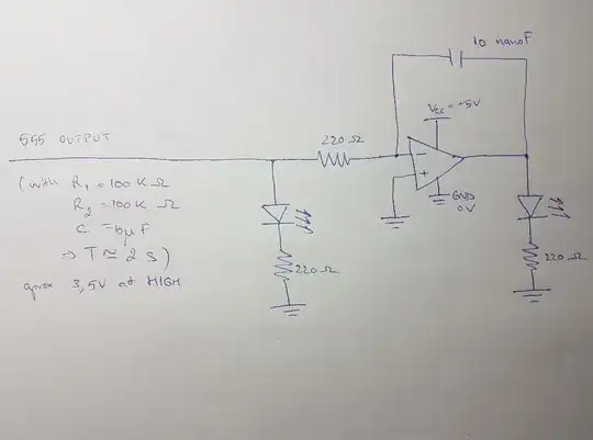
enter image description here
Source: How to amplify and offset the voltage in an opamp?

The gain (or RF/R1) of the INA240A1 is 20V/V

Let's say you have a 1Ohm resistor to measure current on the V+ and V- terminals of the INA240 (and the Vcc set to 5V). If there were 250mA through the resistor then it would be gained by 20 to 5V (which is usually what ADC's want with a 0 to 5V scale). Now lets say you wanted to measure a negative 250mA, well the output would be 0V, because the INA240 is single sided and can't go negative.

So the reference is provided to allow for negative currents to be measured. If Vr is set to half the range (with configuration below) then the 1 ohm resistor would be able to measure a current range of ±125mA

No current across 1 ohm sense resistor is 0mA and 0mV
(0mV*20V/V+2.5V)=2.5V

125mA across 1 ohm sense resistor is 125mV
(125mV*20V/V+2.5V)=5V output on the INA240

Negative 125mA across 1 ohm sense resistor -125mV
(-125mV*20V/V+2.5V)=0V on the INA240
enter image description here
Source: https://www.ti.com/lit/ds/symlink/ina240.pdf

The reference doesn't have to be half of Vcc, it can be set by an external reference, in that case the ranges would change, lets say we use an external reference of 1V:

No current across 1 ohm sense resistor is 0mA and 0mV
(0mV*20V/V+1V)=1V

200mA across 1 ohm sense resistor is 200mV
(200mV*20V/V+1V)=5V output on the INA240

Negative 50mA across 1 ohm sense resistor -50mV
(-50mV*20V/V+1V)=0V on the INA240

So this is why they say it's asymmetric.

Voltage Spike
  • 75,799
  • 36
  • 80
  • 208
0

When I look at the specifications I see "output type:asymmetrical"

The term, in general, could apply to anything such as voltage, current and/or impedance.

Searches found none in either link.
I see no reason for an asymmetric output in an INA.

CMOS logic uses complementary symmetrical impedance output FETs like a half-bridge, using Pch and Nch shared drains. RdsOn is typically 50 Ohms for 5V logic family for both logic states.

For an INA, it serves as a pre-amp and not a power amp so output impedance asymmetry serves no purpose as it might in some high-speed, high-current FET drivers.

I have seen 600V drivers using dual Nch drivers in a half-bridge with asymmetric output impedance. This has the advantage of enabling asymmetric transition times, perhaps to prevent shoot-thru.

  • In an asymmetric output impedance, usually the RdsOn on the high side is higher.

schematic

simulate this circuit – Schematic created using CircuitLab

So unless you provide context to your quote, that is all that can be said. TTL is asymmetric for output impedance being higher on "1"'s.

Tony Stewart EE75
  • 1
  • 3
  • 54
  • 182