2

This is more a theoretical question: Let's say we use a potentiometer as a variable resistor. We can set it from 0% (0Ω) to 100% (let's say 1Ω for simplicity).

Using this pot we can reduce the total range of resistances covered by the 0% to 100% by adding a resistor in parallel. (This results in a non-linear relationship between the position of the wiper and the resistance, but that is fine.) For instance adding 1 ohm resistor we get a maximum of 0.5Ω.

Now I was wondering, is it possible to have a circuit using only resistors to control a larger range of resistances with this potentiometer? (Having 0Ω at 0% is not a requirement!)

My gut feeling is that this is not possible, but I did not manage to prove it.

Circuit fantasist
  • 13,593
  • 1
  • 17
  • 48
flawr
  • 681
  • 6
  • 18
  • @Hearth thanks for pointing out, I put the A at the wrong spot! – flawr Jan 10 '21 at 17:23
  • Exactly how do you define "range"? If the pot (ideally) goes from 0 to x ohms then the range R(max)/R(min) is quite large. – Spehro Pefhany Jan 10 '21 at 17:25
  • @SpehroPefhany I'm interested in the "range" defined by the difference between R(max) and R(min). (And yes, we do assume ideal resistors/pots.) – flawr Jan 10 '21 at 17:29
  • Yes you can, and this is how D/A’s work in small steps or digital pots. There are also partial log pots for audio. – Tony Stewart EE75 Jan 10 '21 at 18:09
  • Can you use a spreadsheet and plot the inverse or nonlinear or asymptotic relationship compared to a linear pot. Then try it with a sig gen and DC biased AC with a common emitter instead of a pot – Tony Stewart EE75 Jan 10 '21 at 18:16
  • I'm pretty sure it's not possible with just passive parts. Anything in series won't change the range and anything in parallel will reduce the range, as you define it. – Spehro Pefhany Jan 10 '21 at 22:10

3 Answers3

0

Generally not. You could switch in series resistors to the combination to make the rheostat a "fine" adjustment control but that requires switches which are out of scope.

One of the practical problems you would encounter is that the power dissipation of the pot may be exceeded at low values. Remember that the power rating is for the whole track. If you use only a fraction of the resistance track then the maximum power dissipation decreases to that fraction of the pot's power rating. Think of it as power rating per unit length or per degree of rotation.

Transistor
  • 168,990
  • 12
  • 186
  • 385
0

I'll take for granted that you measure the resistance between A and B. The first scenario indeed give you a resistance between 0 and 1 ohm. The second, however, give you a range from 1 to 0.5 ohm.

If you wanted to make a 0-0.5ohm pot you would need to place a resistor in parallel with your potentiometer. and not in series with your cursor.

To increase the dynamic range of the potentiometer, you would need to amplify your signal. If such circuit (passive) was known, it would be a game changer in many fields! So I sincerely doubt that it exist! Sorry

Julien
  • 1,717
  • 14
0

It is so wonderful that there are such "theoretical questions" that make us think and reveal the ideas behind mysterious circuits.

When I read this question, my knee-jerk reaction was that this is impossible. But the problem remained dormant in my head, and at some point I began to make a connection with the somewhat strange circuit of an amplifier with a T-bridge in the negative feedback.

Basic idea

... is extremely simple: According to Ohm's law, the current flowing through a resistor R with applied voltage V across it is I = V/R. If we actually supply the resistor with, for example, ten times lower voltage, the current will also decrease ten times (I = V/10R) and it will appear that the resistance has increased ten times (R = 10V/R).

Of course, there is a "small" catch here (as in any circus trick:-) - we see the voltage V when actually a voltage of V/10 is applied.

Implementation

Ohm's circuit with true 10 k resistance

As an example, the current flowing through a 10 k resistor R with applied 10 V voltage V across it is I = 1 mA. We know that the resistance is 10 k but we can also measure the current and calculate the resistance - R = V/R = 10 V/1 mA = 10 k.

schematic

simulate this circuit – Schematic created using CircuitLab

STEP 1

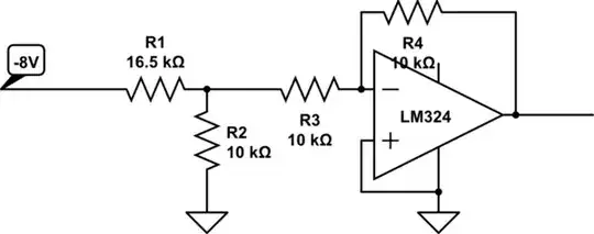
Inverting amplifier with true 10 k R2

As another example, the 10 k resistor R2 and R1 set a gain of -1 of an op-amp inverting amplifier.

schematic

simulate this circuit

STEP 2

Ohm's circuit with virtual 100 k resistance

Now let's apply our trick to virtually increase the 10 k resistance up to 100 k. For this purpose, we connect a low-resistance potentiometer P between the voltage source and R2 and adjust its gain equal to 0.1. As a result, the current decreases to 0.1 mA and we see a 100 k resistance.

schematic

simulate this circuit

STEP 3_1

When we sweep the potentiometer's gain from 0 to 0.9, we see that the "R2" resistance changes from 10 to 100 k but this is actually the total circuit resistance between nodes A and B. In this way, we can say that the P original resistance range (0 ÷ 100 ohms) is expanded to 10 ÷ 100 kohms.

STEP 3_2

Inverting amplifier with virtual 100 k R2

We can see this idea implemented in op-amp amplifiers. For example, the -1 gain of the inverting amplifier above is increased up to -10 by virtually increasing R2 up to 100 k.

schematic

simulate this circuit

STEP 4_1

STEP 4_2

Inverting amplifier with T bridge instead R2

This circuit is usually drawn in a prettier way with the three resistors R2, R3 and R4 grouped together in the shape of the letter "T".

schematic

simulate this circuit

STEP 5

Circuit fantasist
  • 13,593
  • 1
  • 17
  • 48