1

I am trying to find correct fuse for this application.

The purpose of it is to protect current-limiting resistor in case the relay fails to engage. Coincidentally, blown fuse will also prevent further system activation by cycling main power switch, until the problem is fixed and fuse replaced.

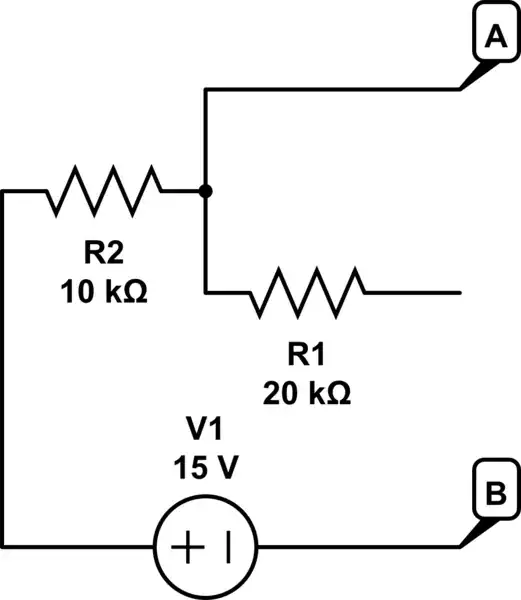
In this circuit the only time current flows through the fuse is when battery is connected. The maximum current is limited to 7-9A (depending on battery charge) by the resistor. However as power capacitors get charged the current quickly drops, and the relay removes fuse/resistor from circuit completely in about 0.1 sec.

Q: Am I correct that current rating of the fuse is pretty much irrelevant in this case, due to very short pulse?

It seems that I2t is defining characteristic here. Unfortunately it cannot be used directly either, as current is not constant. Complicating the matter is that main switch can be triggered several times in a row. The capacitors take about 5 sec to discharge to under 1V, so repeated switching on/off will produce additional power surges.

Any advice on the correct math to be used? I am planning to use 5STP series from Bell Fuse. The requirements are: a) to survive repeated pulses of up to 0.1 sec @ 10A with about 2 sec cool down in between without degradation, and b) to blow when 7A or more is applied continuously for longer than 0.5-1 sec.

Maple
  • 11,755
  • 2
  • 20
  • 56
  • Look at the datasheet for the fuse. They have curves for current and time. You don't have to do a bunch of math (they did it for you). eg. I needed a fuse to blow with a milliseconds long 4.5A pulse. The chart said use an 800ma fuse, it worked like a charm. So in your case, measure the input pulse and choose a fuse that will survive that with a little margin. – Aaron Jan 08 '21 at 22:00
  • @Aaron Interesting. So, what you are saying is that I should choose the fuse by the abnormal condition (relay failure) and hope that being a slow blow type it will survive inrush pulse in normal conditions even if top pulse current may be much higher than current rating of the fuse. This... actually makes sense. It ignores the potential degradation due to repeated over-current pulses in normal operation, but I don't see any info in datasheet that I can use to account for this anyway – Maple Jan 09 '21 at 20:41
  • Look at page 3 of the datasheet you linked to. The average time current curve is what should help you. – Aaron Jan 09 '21 at 23:01

2 Answers2

2

Basically, fuses blow because they get locally hot. Ditto anything else subjected to pulsed power.

You can kind of infer the time constants involved by looking at a current (or power, for some devices) vs. time plot, like the "Average Time Current Curve" in that datasheet. The lines aren't very curved for the first one second or so, from which I infer that the fuse's "main" time constant is over 1s (I'm guessing 2s, by where the line sorta-kinda curves). After that, given that the line is curved up to 10000 seconds, I'm guessing that there's a bazzilion different time constants involved, making life difficult.

If you know the current vs. time as the capacitors charge, then find $$\int_0^{\mathrm{100ms}} i^2 dt$$ This is the size of the current-squared pulse that the fuse undergoes. Divide it by \$100\mathrm{ms}\$ for the behavior of the fuse after \$100\mathrm{ms}\$, and divide it by \$2\mathrm{s}\$ for your "one cycle every \$2\mathrm{s}\$" case. (i.e., find \$\frac{1}{2\mathrm{s}}\int_0^{\mathrm{100ms}} i^2 dt\$)

For the case where the relay fails, find $$\frac{1}{T}\int_0^T i^2 dt$$ for the "average" current up to time \$T\$. Based on the straightness of the current vs. time plot for the first second, this should be pretty good for \$T < 1\mathrm{s}\$ and not too bad out to \$T < 3\mathrm{s}\$ -- I suspect that after that the current will be pretty constant anyway, and you can just read the chart.

TimWescott
  • 44,867
  • 1
  • 41
  • 104
  • I don't have good way to measure real charging curve. I can calculate total energy though, from approximated 10 mF value of the total capacitance on the power lines. (my original estimate of 40 mF turned out to be wrong when I disassembled some of the connected devices) – Maple Jan 08 '21 at 21:33
  • You know R and you know C -- can you just calculate from there? I don't think the total energy going into the cap has a direct relation to the integral of current squared. If it were all being discharged through a resistor into the fuse -- yes. But not, I think, here. – TimWescott Jan 08 '21 at 21:56
0

Your Specs

  • \$10A^2s\$ 5% duty cycle holding energy with tbd Rth to cool fuse terminals.
  • \$25A^2s\$ min trip level
  • Fuse spec from table is ~ \$4* A^2s~to~ 40*\$ (min to max) approx trip level

schematic

simulate this circuit – Schematic created using CircuitLab enter image description here FDMC4D9P20X8

Cheap solution: use a better power supply. (used PC PSU.)

Solve for Fuse size? NOT POSSIBLE

Your trip ( energy )to hold specs are 25/10 but the fuses are 40/4 max/min ratio for trip so this won’t work easily. You would have to heat sink the fuses to reduce their ambient temp and reduce their specs from 10 to 2.5 . I don’t see this is possible. Therefore you will have to make an electronic fuse with more precise energy calculations than the wire can provide to melt the wire’s thermal response deviation.

edit 1

A better design can eliminate the surge and even make it CC, constant current by sensing return current and using a series L and shunt PWM and/or PFM switch to regulate the charge. Do that !

schematic

simulate this circuit

Perhaps something like this "quick and dirty design".

Tony Stewart EE75
  • 1
  • 3
  • 54
  • 182
  • One possibility is for the OP to add a crowbar circuit, to guarantee fuse blows quickly. – Math Keeps Me Busy Jan 08 '21 at 20:29
  • That's is a good electronic fuse – Tony Stewart EE75 Jan 08 '21 at 21:10
  • What if I relax requirements a little? Since capacitors take about 5s to discharge to 1V I can take that as new cool down requirement. Also the resistor [AC03](https://www.vishay.com/docs/28730/acac-at.pdf) has good pulse handling characteristics. All I need from it to not cause fire before fuse blows in one-time catastrophic event. So, 2s @7A seems to be reasonable requirement. – Maple Jan 08 '21 at 21:19
  • @MathKeepsMeBusy considering that the only reason for this circuit is overzealous short protection in specific BMS, I would really like to keep it simple. Hopefully, we'll get better BMS with the next order of batteries. – Maple Jan 08 '21 at 21:42
  • @TonyStewartSunnyskyguyEE75 As I explained before, the only purpose of this circuit is to deal with stubborn "smart" BMS that easily allows up to 80A draw in normal operation but triggers short-circuit protection when battery is connected to the system for the first time, unless we limit the inrush to under 10A. This circuit does not have to protect or regulate anything. Any components capable of 80A constant draw will be huge. Also, there are no dual voltage sources at the time main switch is engaged. In fact, there is nothing but the battery and the switch to work with. – Maple Jan 09 '21 at 21:13
  • I understand. Any components? not true. 1mOhm FETs are small SMD's. Did you consider how this provides soft-start with any current you want by choosing RdsOn , L and diode? Then you decide what voltage you want to engage the relay to bypass the Vin+ to Vout+? why do you doubt? – Tony Stewart EE75 Jan 09 '21 at 22:09
  • @TonyStewartSunnyskyguyEE75 I meant inductor and diode. The FET you mentioned does not meet the requirement for 80A but following your suggestion I found several very interesting options, like TJ200F04M3L. Would you, please, explain what you mean by "min to max trip ratio" and where in datasheet can I find it? The good part of using P-FET based inrush limiter is that I would not need a fuse to protect resistor anymore. The bad part is that all examples I've found have same problem of time-setting capacitor not discharging quick enough when main switch triggered off and on again – Maple Jan 11 '21 at 06:17
  • These ratios determine the dynamic range which exceeds your spec.. you must choose the cap values for the time you need. That’s all. – Tony Stewart EE75 Jan 11 '21 at 13:18