3

I need a circuit/IC that can generate a single pulse with a variable pulse width (I would want a minimum of 50 ns but if that is not possible the next minimum can be 1 μs, and even if that is not possible then the final minimum can be 5 μs, depending on the achievable minimum, correspondingly the max can be 5 μs, 5 ms, 25 ms respectively) and variable amplitude with both positive and negative pulses in a range of ±5 V (practically the operation would be in ±2 V range) with a resolution of at least 10-20 mV. The variables need to be digitally controlled (preferably) but this is not a requirement. The current output can be a maximum of 2-3 mA. So I have searched a lot of the pulse generator ICs (monostable) available from different websites and companies (analog devices, data delay, maxim, etc) for 4 days now and I don't have anything that is the proper solution. All of them have variable pulse width and ± pulses which is good but the amplitude is the same as supply voltage and is not variable which is not good for me.

Here are the links to a few of the pulse generators I have searched for:

LTC6993

DS1040

Data delay devices 3D3608 & 3D3612

The closest I have come to some potential solutions (might be wrong) are:

A. Pick any monostable multivibrator (such as LTC6993) and do either of the following for amplitude downscaling:

  1. Use an 'AC voltage divider' or a 'Capacitor voltage divider' as mentioned in this answer. But I am not sure if this is the right way or if I should be careful about something such as drive current or capacitance of the pulse generator IC.

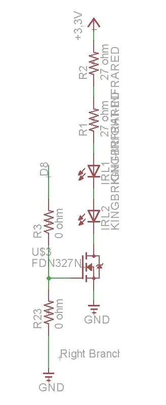
  2. Use the output pulse (with an amplitude of 3.3 V / 5 V) of the monostable pulse generator to control the gate of a MOSFET with a lower drain-source voltage (typically 0.5-2 V) generated by a DAC.

B. Use a DAC to generate the (one-shot) pulse directly, I am not sure if it is possible to do this accurately (like a 1 μs pulse). If it possible, what kind of sampling rate/settling time/speed specifications I am looking for?

Thank you for reading everything. If you have a solution/advice (in form of a component, circuit, or a suggestion) please let me know, I would really appreciate it.

ilkkachu
  • 1,067
  • 8
  • 8
paulplusx
  • 314
  • 3
  • 16
  • 1
    What **accuracy** and **resolution** do you expect for pulse width? What **accuracy** do you expect for output voltage? – Elliot Alderson Jan 06 '21 at 13:18
  • Which of those you found that matched *All of them have variable pulse width and ± pulses* do you consider the best potential candidate as a starting point when adding an extra amplitude control feature. Leave a data sheet link. – Andy aka Jan 06 '21 at 13:20
  • 2B will be the cheapest and most configurable, assuming that you have a fast-enough controller. – Reinderien Jan 06 '21 at 15:08
  • @ElliotAlderson. The accuracy is not much of a concern and need no be super high. Maybe a 1uS pulse can deviate between ± 0.2-0.3uS. It would be good to have a resolution of 50nS/500nS/1uS (depending on the lowest possible pulse width being 50nS/500nS/1uS respectively.) but again that is also not that much of a concern for now. I am looking for an idea or a circuit or an IC to correctly generate, lets say a 1uS, 500mV one-shot pulse that can drive with upto 2mA. – paulplusx Jan 06 '21 at 16:06
  • @Andyaka Sorry for being a bit vague. What I meant is all of the pulse generator ICs (digitally programmable or not) are similar to a simple monostable multivibrator IC made out of a 555 timer in which the amplitude of the pulse is similar to the supply voltage and with no option to change the amplitude of the output pulse. I'll leave a few datasheets in a new edit. – paulplusx Jan 06 '21 at 16:10
  • @Reinderien B is actually a different option altogether. I edited it. Really sorry for the initial wrong formatting. I hope that doesn't affect your response, if it does, please let me know. The pulse generators would be controlled by an FPGA – paulplusx Jan 06 '21 at 16:12
  • _1uS or higher, if possible 50ns or higher_ - So like... 60 seconds included? Can you provide actual upper and lower bounds? – Reinderien Jan 06 '21 at 16:20
  • @Reinderien Really sorry for being that vague, I was just looking out for different options if one is not available. So let me just say that ideally, I would want a minimum of 50ns but if that is not possible the next minimum can be 1uS, and even if that is not possible then the final minimum can be 5uS. I hope that clears it up a bit. – paulplusx Jan 06 '21 at 16:25
  • 50ns minimum; and what maximum? This will inform your implementation. – Reinderien Jan 06 '21 at 16:26
  • Let us [continue this discussion in chat](https://chat.stackexchange.com/rooms/118123/discussion-between-reinderien-and-paulplusx). – Reinderien Jan 06 '21 at 16:28

3 Answers3

5

Just add another component:

  1. Pick any monostable multivibrator that can generate a pulse with the desired timing characteristics;
  2. pick any (slow) two-channel DAC to generate the two desired, constant output voltages (if one output voltage is always GND, you need only one channel);
  3. use an analog multiplexer (random example: TS12A12511) to switch the output between the voltages.

If the DAC's outputs are too weak, add buffers before or after the switch.

CL.
  • 18,161
  • 5
  • 40
  • 67
  • I don't think the analog switch you linked will be fast enough to preserve accurate pulse widths down to 50ns. – Elliot Alderson Jan 06 '21 at 14:28
  • Thank you for your answer. I would need a few clarifications from your answer: 1. When you say 'two constant output voltages', do you mean that would be the output high and output low between which, the output pulse would be generated or do you mean like configure one voltage for positive pulses and another voltage for negative pulses? 2. If I am understanding it correctly, the control/trigger of analog mux is done with the output pulse of the monostable multivibrator? – paulplusx Jan 06 '21 at 16:22
  • 1. It is not clear whether you want two or three voltages. You need one DAC channel for each configurable output voltage that must be available for the same pulse. 2. Yes. – CL. Jan 06 '21 at 21:24
  • I have a concern. Will the signal integrity be maintained (as Elliot Alderson pointed out)? Will there be significant jitters or some other switching problems? Which spec of the Analog MUX should be the limiting parameter here? I mean which parameter should I look out for if going from a longer to a shorter pulse (for a faithful representation of the trigger pulse)? – paulplusx Jan 07 '21 at 15:52
  • The datasheet specifies a turn-on time, which should be similar for both channels. I do not know of any device that specified the jitter; you have to measure yourself. – CL. Jan 08 '21 at 09:47
  • @CL. One final thing. Can I use an SPST instead of SPDT and pull the output to the ground when the switch is off? So when the switch is on, it would give the DAC output and when it is off it would be ground. Would this work? – paulplusx Jan 13 '21 at 12:34
  • That pulldown would have to be strong enough to drive 2 mA. Would it be allowed for the output to have asymmetric drive strength? – CL. Jan 13 '21 at 18:07
4

This is a perfect use case for a microcontroller, DAC, and a voltage controlled amplifier. With minimal load, an AB audio amp and SPI or on-die dac I estimate your system will hit the 1 us single shot requirement with appropriate firmware on an 8 bit MCU.

crasic
  • 5,797
  • 1
  • 20
  • 43
  • Thanks for your answer. Are you suggesting that I generate the pulse directly with a DAC (as mentioned in my option B) or something else? Also, What is the role of the voltage-controlled amplifier over here? Could you please elaborate on your answer? – paulplusx Jan 06 '21 at 17:08
  • 1
    Yes, generated directly by DAC. The amplifier represents a common building block to get bipolar operation out of a single ended dac or simple resistor ladder solution, a bipolar dac could be used as well and if the output range is suitable could be considered . There are other many other coupling options that could be considered depending on requirements (e.g. jitter and phase delay) but this is the simplest for your gross requirements. – crasic Jan 06 '21 at 17:19
3

Do as much as possible in the FPGA that you already have:

Since there is a 100MHz clock, the period is 10ns. The minimum counter division is 5, which is easy, getting to 50ns. The maximum counter division for your stated 25ms is 2,500,000.

$$\text{ceil} \left( \log_2 \frac {25\text{ms}} {10\text{ns}} \right) = 22$$

You need a minimum 22-bit counter in your FPGA, which is also easy.

The simplest output stage is a parallel-connected passive R2R ladder connected to a high-speed op-amp buffer - two components. The Zedboard does not come with an integrated DAC so these components will need to be off-board.

For 10mV in a 4V range,

$$\text{ceil} \left( \log_2 \frac {4\text{V}} {10\text{mV}} \right) = 9$$

$$ \frac {4 \text{V}} {2^8} = 15.6 \text{mV} $$

which is within your 10-20mV requirement. 8-bit R2R DACs are common enough but you'll want to test thoroughly for linearity and monotonicity.

Since you need double-ended (negative rail to positive rail) output, you could reconfigure your op-amp to have a super-unity gain and accept double-ended power supply. This comes with a list of caveats, including: scaling your resistors will be influenced by their interaction with the input capacitance of the op-amp, so mind its slew rate and input capacitance declarations. The example values below scale from a DAC voltage of 0-5 to a working output of -2 - 2. Having a buffer U1 between your R2R DAC and R1 is important.

schematic

simulate this circuit – Schematic created using CircuitLab

Alternatively, pay more for an integrated DAC such as the TI DAC8581. This DAC supports +/- 5V bipolar output but requires 650ns to settle. You will find it challenging to get an integrated DAC that is much faster.

Reinderien
  • 3,102
  • 16
  • 28
  • Thanks for your answer. I have stated the voltage resolution in my question, it's between 10-20mV for a range of ±2V (more generally ±5V). Are you suggesting that I use the generated pulse as a reference input to the R2R ladder? In that case, Don't you think for such a small pulse width, the output might get distorted by a resistor voltage divider? – paulplusx Jan 06 '21 at 17:04
  • My mistake. I've edited to show some example integrated R2R packages that "should" work for your purposes. – Reinderien Jan 06 '21 at 17:12
  • Thank you, I'll have a look. Also, what do you think about negative pulses? – paulplusx Jan 06 '21 at 17:14
  • For negative pulses see edit including example op-amp configuration. Or pay for a double-ended output DAC. – Reinderien Jan 07 '21 at 22:47