0

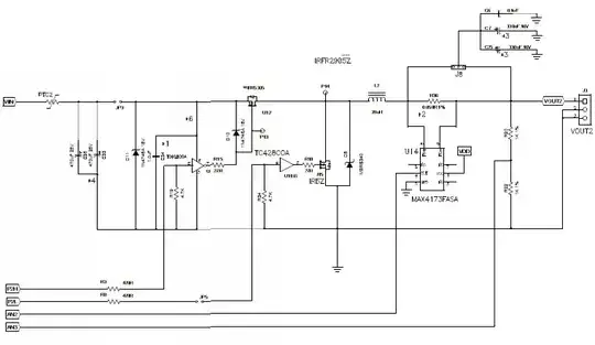
From Figure 1 is evident that to get the dead time I must define the values for RC. E.g my resistor is 220 ohms and capacitor is 0.1uF this gives me 22us at 1-time constant, however, when I measure this on my Pico scope this shows roughly 6.5us at the point of the dead time. Could some one help me understand where the 6.5uS comes from when using these values please ?

Figure 1

Image source: How is dead time in a half bridge implemented.
Transistor
  • 168,990
  • 12
  • 186
  • 385
Daniel Bashy
  • 154
  • 3
  • 15
  • Depends on the voltage levels those gates perceive as logic 0 and 1. Which gates are they? – Unimportant Jan 02 '21 at 10:46
  • Can you link the source of the picture please. – Andy aka Jan 02 '21 at 10:50
  • Hi Andy I got the picture from you, I am not sure how to link the source to you – Daniel Bashy Jan 02 '21 at 11:00
  • It is clearly some fraction of the RC time constant. That fraction is determined by the logic level thresholds of your gates. –  Jan 02 '21 at 11:24
  • @DanielBashy - that's why I asked because I should have said (in the picture source) that schmitt trigger gates are recommended. You can copy and paste the link into a comment. Like this: https://electronics.stackexchange.com/questions/503865/how-is-dead-time-in-a-half-bridge-implemented/503871#503871 - and note that does show the gates being schmitt triggers. – Andy aka Jan 02 '21 at 11:38
  • @DanielBashy - was it this one: https://electronics.stackexchange.com/questions/109747/isolating-pwm-from-h-bridge/109748#109748 - I do mention schmitt trigger gates. – Andy aka Jan 02 '21 at 11:41
  • Hi Andy yes it is from that link, I know you said use Schmitt trigger gates, but I don't understand how to select the RC values to give me for example 0.2us dead-time? – Daniel Bashy Jan 02 '21 at 12:49

1 Answers1

4

I have a slightly different circuit than the one proposed by Andy. I used it many times in half-bridge circuits for providing adequate deadtime. I considered a 5-V level for the clock while the AND gates being supplied by a 5-V \$V_{cc}\$ toggle at 2.5 V. If you use different gates, you can modify the below calculations accordingly:

enter image description here

In this example, the macro calculates a 289-pF capacitor for the wanted 200-ns deadtime.

enter image description here

Verbal Kint
  • 20,420
  • 1
  • 16
  • 50