I was reading this post How are positive and negative feedback of opamps so different? How to analyse a circuit where both are present? for identifying positive/negative feedback of op-amp circuit.
Consider the circuit shown in figure(1):
simulate this circuit – Schematic created using CircuitLab
According to the approach suggested by nidhin:
$$v_-=v_{in}=1.6 \quad (\text{by inspection})$$
$$v_+=\frac{4}{3+4}v_o=\frac{4}{7}v_o$$
Now substituting in the formula: \$ v_{o}=A_{ol}(v_+−v_−)\$ , we get:
$$v_{o}=A_{ol}(\frac{4}{7}v_o− 1.6)$$
$$\implies v_o (1- \frac{4}{7}A_{ol} )=-1.6 A_{ol}$$
$$\implies v_o =\frac{-1.6 A_{ol}}{1- \frac{4}{7}A_{ol} }$$
$$\implies \frac{v_o}{1.6} =\frac{- A_{ol}}{1- \frac{4}{7}A_{ol} }$$
$$\text{so, } A_{cl}=\lim_{A_{ol}\to \infty} \frac{v_o}{v_{in}} =\lim_{A_{ol}\to \infty} \frac{v_o}{1.6}=\lim_{A_{ol}\to \infty} \frac{- A_{ol}}{1- \frac{4}{7}A_{ol} }=\frac{-1}{- \frac{4}{7} }=1.75$$
Now, as \$ A_{cl}\$ is finite , \$ \implies \$ net feedback is negative
But according to the approach suggested by Alfred Centauri:
Assume there is a net negative feedback, \$\implies \$ the non-inverting and inverting input voltages are equal
$$\therefore 1.6=\frac{4}{7}v_o$$
$$\implies v_o= 2.8$$
However, $$ A_{cl}= \frac{v_o}{v_{in}}=\frac{2.8}{1.6}= 1.75>0 $$
which is a \$ {\color{red}{\text{red flag}}} \$ since inverting-amplifier should have negative gain
Hence, our assumption is wrong
so according to this approach, net feedback is positive
which is making me confused;
Hence,
1)Identify the net feedback in figure(1) with explanations
2)If the circuit in figure(1) is in net negative feedback, then where did i make a mistake in implementing Alfred's ideas, or
If the circuit in figure(1) is in net positive feedback, then where did i make a mistake in implementing nidhin's ideas
UPDATE:
If we use a non-ideal voltage source \$ V_{in}=1 \$ volt with \$ R_s =1 K \Omega \$ , i.e,
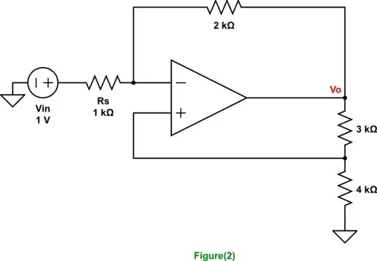
simulate this circuit
then, please explain the type of feedback