simulate this circuit – Schematic created using CircuitLab
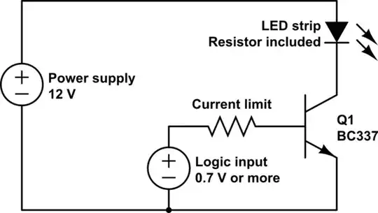
To start I am very new to working with electronics, I've read a little theory and thats about it. My goal was to make a circuit with a BC337 transistor in it acting like a switch. My goal was that a logic cell, which outputs 3.3V would be able to control the flow of power for a 12V LED chain of lights.
I hoped to use the 3.3V to control the base of the transistor which would enable the 12V to flow(or not) from the collector to the emitter so I wired the positive end of the 12v to the collector, the 12v ground to the emitter, and was about to connect the positive wire of the 3.3V to the base when I realized I had not figured out a place for the negative end of the 3.3V.
So my question is this: Where do I place the negative end of the 3.3V base on my transistor, so that the transistor can still be controlled by the 3.3V and that the voltage of the emitter will still be 12V(or at least very close)?
I tested several configurations of where the negative end could go but all of them either didn't work or resulted in reduced emitter voltage: 9V or less. I do not know if it is relevant but my 12v comes from a 1.5A wall voltage converter and my 3.3V comes from a coin battery. Any help would be appreciated thank you.