0

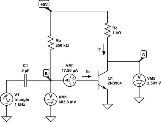
I am trying to measure light intensity using a photodiode (S1336-18BQ) connected to an op-amp (LF412CP) in transimpedance amplifier configuration. I couldn't get it to work correctly, so I started searching for problems and have found something very peculiar: there is a current flowing from the negative input of the op-amp. The value of the current is the same order of magnitude as the short-circuit current of the photodiode under the same conditions (~1 µA).
schematic

simulate this circuit – Schematic created using CircuitLab

I have very little experience in analog electronics, but I understand that inputs of an op-amp (especially a JFET one) should have very high impedance. I have tried three identical op-amps to ensure that it is not just a damaged chip. Please forgive me if I am asking something obvious.
CreFroD
  • 43
  • 8

3 Answers3

8

enter image description here

The op-amp you have chosen (LF412) is unsuitable for the power supply regime you show in your schematic. The input common-mode voltage range is a couple of volts inside the power rails hence putting the non-inverting input to ground (also your negative supply rail) is a mistake - you need bipolar supplies for this op-amp.

In addition, the minimum supply recommended for this op-amp is +/- 5 volts (a span of 10 volts) and you are showing it on a single 5 volt rail: -

enter image description here

This op-amp won't work properly on a single 5 volt rail.

Andy aka
  • 434,556
  • 28
  • 351
  • 777
4

It does not work with single 5V supply.

Datasheet says minimum supply voltage for LF412CP is +/- 3.5V

The circuit is also exceeding the common mode input voltage range. It does not go down to negative supply voltage.

Justme
  • 127,425
  • 3
  • 97
  • 261
0

If you still want a single-supplied circuit, try this clever H&H circuit solution (Page 253, Fig. J):

AE Photodiode converter

I have explained it in my answer to a similar question two years ago. The role of the second resistor R2 is to "lift" the voltage drop across the "floating" photodiode above the ground thus ensuring a kind of a "self-biasing".

I have illustrated the circuit operation by means of voltage bars (in red) and current loops (in green). Looking at the picture now I think the voltage across the photodiode should have an opposite polarity.

Circuit fantasist
  • 13,593
  • 1
  • 17
  • 48