5

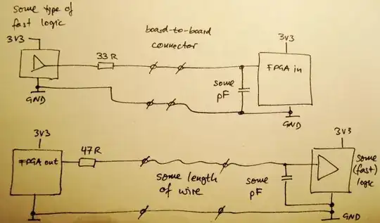
Is it good practice to slow down the slew rate of a CMOS output by putting an RC filter on it? What happens with impedance matching after I do this? Or can I just set the RC filter with such a low cut-off that transmission line effects don't need to be considered?

The CMOS output that is concerned here has a minimum 10-90% rise time of 1ns. Since I am running a trace that is around 250mm from this output, I want to minimize signal integrity issues.

zebonaut
  • 18,170
  • 4
  • 60
  • 104
cksa361
  • 3,814
  • 7
  • 33
  • 49

2 Answers2

3

Sure, and it's not as uncommon as you may think.

You use it mostly when impedance matching is not an option, e.g. because you are forced to break your impedance-controlled transmission lines when running them over connectors or wires.

FPGA outputs are often very fast, and if there's a bit of a trace length involved, you can ad a 22...50 Ohm resistor in series, and put a small capacitor (10...100 pF) between the next chip's input and GND. Also good if done the other way round (capacitor at FPGA input).

Examples include, but are not limited to: enter image description here

This avoids ringing, and most importantly, it may keep the voltage from swinging below GND or above VCC. Some logic families (or FPGA inputs) are quite sensitive when it comes to under- and overshoot.

Compared to real, impedance controlled traces, it's a nasty hack, of course, but it's still way better than severe ringing on an input.

zebonaut
  • 18,170
  • 4
  • 60
  • 104
1

Quite often, you just need the R, as a series termination to the line (which provides all the C necessary).

Provided this is a point-to-point connection, and not a complex tree with loads close to the driver, this is safe and simple. R + driver output Z can either be matched to the nominal trace impedance; or somewhat higher to reduce the slew rate.

Make sure there is a good direct earth return path! (ground plane is best but not the only way) What matters is to keep the loop area (between signal and ground) small. For example, run a ground next to the signal, or either side of it, or the other side of the PCB directly under it, or twist signal and ground wires together.