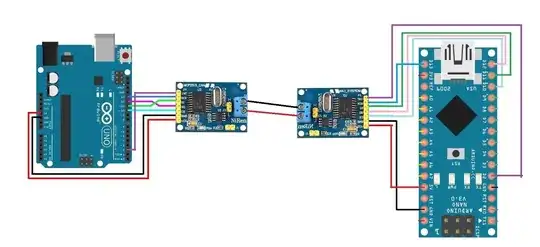
So firstly, you'll have to excuse my lack of electronic knowledge and popper terminology, this is my first crack at anything outside of the software world.
I have 2 MCP2515 CAN Transceivers (the cheap Chinese ones), an Arduino Uno and an Arduino Nano. I'm trying to replicate the Seeed Studio tutorial on a CAN BUS simulation here. However, I am having trouble using a baud rate higher than 125kbps. When I later expand this project to talk to my car, I need the baud rate to be at 500kbps as that is the rate my car is supposedly transmitting at, so I would like to at least get the simulation running as I would expect in the real world.
The two transceivers are connected via jumper wires to the High and Low, while the Arduino's are connected to their appropriate positions (MISO, MOSI, CS, SCK, INT, 5V and GRD). Please see the (poorly illustrated) circuit diagram below.
(edit: fixed CAN connection in diagram)

So using the code from the Seeed Studio tutorial (below), I modify the correct CS pin to be 10 (in both places just to be sure):
SPI_CS_PIN = 10
Then I must set the MCP baud rate to no higher than 125kbps, else the master and slave will not communicate properly.
I upload the "send" code to the Nano and the "receive" code to the Uno. When the baud rate is set to 125kbps I have no issues; however, when the baud rate is set to 250 or 500kbps, the Nano says it is sending data, but the Uno does not receive any. I have tried switching their roles and using different libraries; however, the result is always the same.
I read that CAN Low is limited to 125kbps, but I'm not educated enough to know how that would be limiting me (if at all) in this situation.
Can anyone make any suggestions as to how I can overcome this? Is it possible I just have some bad clones or could there be something else?
Thanks
SEND:
// demo: CAN-BUS Shield, send data
// loovee@seeed.cc


#include <SPI.h>

/*SAMD core*/
#ifdef ARDUINO_SAMD_VARIANT_COMPLIANCE
    #define SERIAL SerialUSB
#else
    #define SERIAL Serial
#endif


#define CAN_2515
// #define CAN_2518FD

// the cs pin of the version after v1.1 is default to D9
// v0.9b and v1.0 is default D10

// Set SPI CS Pin according to your hardware
// For Wio Terminal w/ MCP2518FD RPi Hat:
// Channel 0 SPI_CS Pin: BCM 8
// Channel 1 SPI_CS Pin: BCM 7
// Interupt Pin: BCM25
// *****************************************
// For Arduino MCP2515 Hat:
// SPI_CS Pin: D9

#ifdef CAN_2518FD
#include "mcp2518fd_can.h"
const int SPI_CS_PIN = 10;
const int CAN_INT_PIN = 2;
mcp2518fd CAN(SPI_CS_PIN); // Set CS pin
#endif

#ifdef CAN_2515
#include "mcp2515_can.h"
const int SPI_CS_PIN = 10;
const int CAN_INT_PIN = 2;
mcp2515_can CAN(SPI_CS_PIN); // Set CS pin
#endif                              // Set CS pin

void setup() {
    SERIAL.begin(115200);
    while(!Serial){};

#ifdef CAN_2518FD
    while (0 != CAN.begin((byte)CAN_500K_1M)) {            // init can bus : baudrate = 500k
#else
    while (CAN_OK != CAN.begin(CAN_500KBPS)) {             // init can bus : baudrate = 500k
#endif
        SERIAL.println("CAN BUS Shield init fail");
        SERIAL.println(" Init CAN BUS Shield again");
        delay(100);
    }
    SERIAL.println("CAN BUS Shield init ok!");
}

unsigned char stmp[8] = {0, 0, 0, 0, 0, 0, 0, 0};
void loop() {
    // send data:  id = 0x00, standrad frame, data len = 8, stmp: data buf
    stmp[7] = stmp[7] + 1;
    if (stmp[7] == 100) {
        stmp[7] = 0;
        stmp[6] = stmp[6] + 1;

        if (stmp[6] == 100) {
            stmp[6] = 0;
            stmp[5] = stmp[6] + 1;
        }
    }

    CAN.sendMsgBuf(0x00, 0, 8, stmp);
    delay(100);                       // send data per 100ms
    SERIAL.println("CAN BUS sendMsgBuf ok!");
}

// END FILE
RECEIVE:
// demo: CAN-BUS Shield, receive data with check mode
// send data coming to fast, such as less than 10ms, you can use this way
// loovee, 2014-6-13


#include <SPI.h>
/*SAMD core*/
#ifdef ARDUINO_SAMD_VARIANT_COMPLIANCE
    #define SERIAL SerialUSB
#else
    #define SERIAL Serial
#endif

#define CAN_2515
// #define CAN_2518FD

// the cs pin of the version after v1.1 is default to D9
// v0.9b and v1.0 is default D10

// Set SPI CS Pin according to your hardware
// For Wio Terminal w/ MCP2518FD RPi Hat:
// Channel 0 SPI_CS Pin: BCM 8
// Channel 1 SPI_CS Pin: BCM 7
// Interupt Pin: BCM25
// *****************************************
// For Arduino MCP2515 Hat:
// SPI_CS Pin: D9

#ifdef CAN_2518FD
#include "mcp2518fd_can.h"
const int SPI_CS_PIN = 10;
const int CAN_INT_PIN = 2;
mcp2518fd CAN(SPI_CS_PIN); // Set CS pin
#endif

#ifdef CAN_2515
#include "mcp2515_can.h"
const int SPI_CS_PIN = 10;
const int CAN_INT_PIN = 2;
mcp2515_can CAN(SPI_CS_PIN); // Set CS pin
#endif

void setup() {
    SERIAL.begin(115200);

#ifdef CAN_2518FD
    while (0 != CAN.begin((byte)CAN_500K_1M)) {            // init can bus : baudrate = 500k
#else
    while (CAN_OK != CAN.begin(CAN_500KBPS)) {             // init can bus : baudrate = 500k
#endif
        SERIAL.println("CAN BUS Shield init fail");
        SERIAL.println(" Init CAN BUS Shield again");
        delay(100);
    }
    SERIAL.println("CAN BUS Shield init ok!");
}


void loop() {
    unsigned char len = 0;
    unsigned char buf[8];

    if (CAN_MSGAVAIL == CAN.checkReceive()) {         // check if data coming
        CAN.readMsgBuf(&len, buf);    // read data,  len: data length, buf: data buf

        unsigned long canId = CAN.getCanId();

        SERIAL.println("-----------------------------");
        SERIAL.print("Get data from ID: 0x");
        SERIAL.println(canId, HEX);

        for (int i = 0; i < len; i++) { // print the data
            SERIAL.print(buf[i], HEX);
            SERIAL.print("\t");
        }
        SERIAL.println();
    }
}

/*********************************************************************************************************
    END FILE
*********************************************************************************************************/