I was trying to do a project in Proteus Desing Suite which needs to use a Matrix LED Display with size of 8x8 using MAX7219 SPI Interface. The problem occurs when I try to simulate it.
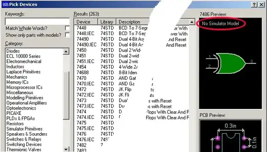
I'm trying to do a smiley face but the software always show me all the dots are ON, doesn't care what values I send to the MAX7219. I show here an screenshot:
I tried to do something similar with a two 7-segment Display LCD and the result is better, I get the correct values, but then both start flickering.
Code I'm using:
/* Main.c file generated by New Project wizard
 *
 * Created:   do. dic. 20 2020
 * Processor: STM32F103C6
 * Compiler:  Keil for ARM
 */

#include <stm32f103x6.h>

/*int main (void)
 {
   // Write your code here
   while (1)
      ;
   return 0;
 }
*/

void delay_ms(uint16_t t){
    uint16_t i;
    volatile unsigned long j;
    for (i = 0; i < t; i++)
        for (j = 0; j < 6000; j++);
}

void spi1_init(void);
uint8_t spi1_transfer(uint8_t d);
void max7219_send(uint8_t cmd, uint8_t data);

uint8_t i, j;

//uint8_t smile[8] = {0x3C,0x42,0xA5,0x81,0xA5,0x99,0x42,0x3C};
uint8_t smile[] =          // fill array for the smiley
{
0x3e,//0b00111110,
0x41,//0b01000001,
0x95,//0b10010101,
0xA1,//0b10100001,
0xA1,//0b10100001,
0x95,//0b10010101,
0x41,//0b01000001,
0x3e,//0b00111110
};


int main( ) {
    RCC->APB2ENR |= 0xFC;   /* enable clocks for GPIO */

    spi1_init(); /* initialize the SPI module */

    //DISPLAY 7 SEGMENT
    /*
    //max7219_send(0x09, 0xFF); // enable decoding for all digits
    max7219_send(0x09, 0x02);   // enable decoding for digit2 and disable for digit1
    max7219_send(0x0B, 1);      // 2 (1+1) digits
    max7219_send(0x0C, 0x01);   // turn on

    //max7219_send(0x01, 9);    // show 9 on digit 1
    //max7219_send(0x02, 4);    // show 4 on digit 2
    max7219_send(0x01, 0x3E);   // show U on digit 1
    max7219_send(0x02, 2);      // show 2 on digit 2
    */

    //DISPLAY MATRIX 8x8

    max7219_send(0x09, 0x00);   // disable decoding for all digits
    max7219_send(0x0B, 7);      // scan digits 0 to 7
    max7219_send(0x0C, 0x01);   // turn on

    for (i = 0; i < 8; i++){
        max7219_send(i+1, smile[i]);
    }

    while(1) { }
}

/* The function initializes the SPI module */
void spi1_init()
{
    RCC->APB2ENR |= 0xFC|(1<<12);   /* enable clocks for GPIO and SPI1 */
    GPIOA->CRL = 0xB4B34444;    /* MOSI (PA7) and SCK(PA5): alt. func. out, PA4: output for CS */
    SPI1->CR1 = 0x35C;  /* SPE = 1, BR = 3, FFD = 0, SSI and SSM = 1 */
}

/* The function sends a byte of data through SPI */
uint8_t spi1_transfer(uint8_t d)
{
    SPI1->DR = d;   /* send the contents of d */
    while((SPI1->SR&(1<<0)) == 0);  /* wait until RXNE is set */
    return SPI1->DR;    /* return the received data */
}

void max7219_send(uint8_t cmd, uint8_t data)
{
    GPIOA->BRR = (1<<4);    /* Enable Chip Select */
    spi1_transfer(cmd);
    spi1_transfer(data);
    GPIOA->BSRR = (1<<4);   /* Disable Chip Select */
}
I would like to know if I can solve at least one of the problems, but the first is my priority (show the correct dots on in the 8x8 Matrix LED), maybe is because of too slow/fast refresh? Anyways, I can't figure out how to solve it, so any helps would be nice, thanks in advance!
The base code is extracted from this site: https://nicerland.com/stm32f103/
And the project I am doing can be downloaded here: https://www.mediafire.com/file/k0rw8x72s05wehb/TP4_PRUEBA_00_21122020.zip/file


