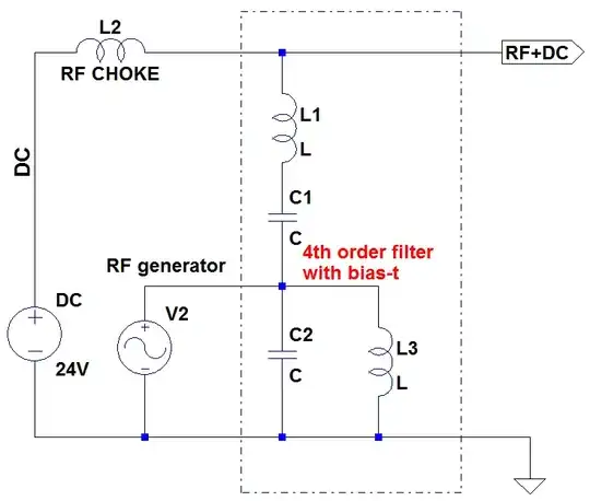
I'll assume that the RF portion of the circuit is laid out with the normal considerations for EMC in RF, and you're asking about any special considerations related to the fact this circuit is a bias-tee.
An added DC voltage/current on an RF circuit doesn't add any particular extra EMC risks to the RF circuit.
On the other hand, if some of your RF leaks in to the DC portion of the circuit (in this case, basically the traces/wires back to the 24 V battery), then it you could have a problem. Mainly because that portion of the circuit is probably not designed so well to minimize EMI.
I'd say the best way to reduce this risk is to be sure you won't leak rf power into the dc circuit. The main way this can happen is through inter-winding capacitance of the choke inductor. Make sure you know what is the inter-winding capacitance for your inductor and make an estimate of how much rf will leak out before you proceed. Unfortunately I can't really give you a rule of thumb for how much leakage is too much --- only an idea about what issues you need to think about.
Edit
Your edited question asks about electromagnetic susceptibility. The regulations on susceptibility generally say something like, "operation of your system should not be disrupted by conforming radiators in its environment." Since the circuit you're designing is composed entirely of passive components, its unlikely to be disrupted, even by quite strong nearby radiators.
That said, maybe you're concerned about signals being picked up by your circuit and transmitting down the line to the connected equipment. Good rf design to suppress radiation will also give good susceptibility performance, so I won't say more about that.
You might be especially concerned about your choke inductor picking up magnetic fields from nearby mains wiring. I've never seen this in real life, but then again I've never worked with such a low rf frequency and the corresponding big inductor you'll need for the choke.
But I can at least make a suggestion: Add locations on board for a filter to catch the mains frequency in whatever location you'll install the circuit. Initially, build the device without any filter, and measure the performance. If you do have a problem, then stuff the components to add the filter.
If the inductor picks up magentic signals, it will act like a current source. So you need the filter to either act like an open in series with the inductor at resonance, or a short in parallel to prevent the interference signal from reaching the rest of the circuit. The series filter solution is probably a bad idea because its inductor will need to be oversized to deal with your 4 A DC currents. That leaves a shunt filter configuration:
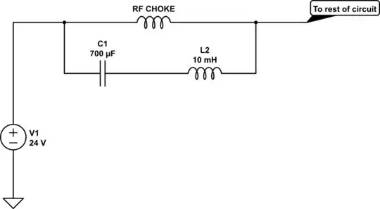
From a quick search I found a 10 mH inductor available at reasonable cost with 19 Ohm series resistance. That was enough to broaden the response of this filter out to give relatively low impedance from 10 to 200 Hz. Of course the impedance minimum is given by the series resistance. You may want to search out a lower-resistance coil to reduce the minimum impedance and increase the impedance at your 130 kHz rf frequency. You'll want to simulate this with the rest of your circuit to nail down the details and make final part selections.