9

I'm considering doing DIY SMT Reflow for production of my Super OSD project.

An overview of the component count:

  • Resistors: ~50 x 0603; precision 0.1% resistors as well as 1% and 5% components
  • Capacitors: 17 x 0603, 2 x 0805, 1 x 1206 (all ceramics), 2 x EIA-3216 (tantalums.)
  • Inductors: 1 SDR-0604 package
  • Chips: SOIC-8 (EEPROM), SOIC-28, TQFP-44, some SOT-23 (temp sensor + TL431.)
  • Transistors: 3 x SOT-23 (2 x N-ch mosfet, 1 x NPN)
  • Diodes: 2 x SOT-23, 2 x SOD-323
  • Misc: polyfuse 0805 x 1, LED 0603 x 1

As can be seen this going to be a monster to solder manually so I was thinking of doing DIY toaster oven reflow. Would this be suitable? Are there any pitfalls I need to be aware of?

Otherwise I'm going to have to solder them up myself but I see it being a real problem with almost 80 tiny components per board.
Thomas O
  • 31,546
  • 57
  • 182
  • 320
  • 1
    You mention you want to sell these for $70 with the costs of parts+PCB being around $45. I think you should realize there's not profit in this at all? Have a look here: http://www.eevblog.com/2010/11/15/eevblog-127-pcb-design-for-manufacture-tutorial/. Also, see Dave's microcurrents (uCurrent - http://eevblog.myshopify.com/) - they sell for $75 with much less components but all PCB manufacturing & testing outsourced (in batches of a few hundred I think). I think Dave would barely make a profit from this. – RJR Dec 04 '14 at 02:36
  • Related question: http://electronics.stackexchange.com/questions/1184/diy-smt-reflow-toaster-oven-skillet-or – Toby Jaffey Oct 19 '10 at 23:13

3 Answers3

12

If you can get hold of a dissecting scope and some decent tweezers, you could probably solder all those parts in about 2 hours. I've done a similar board with around 125 components in about 3 hours.

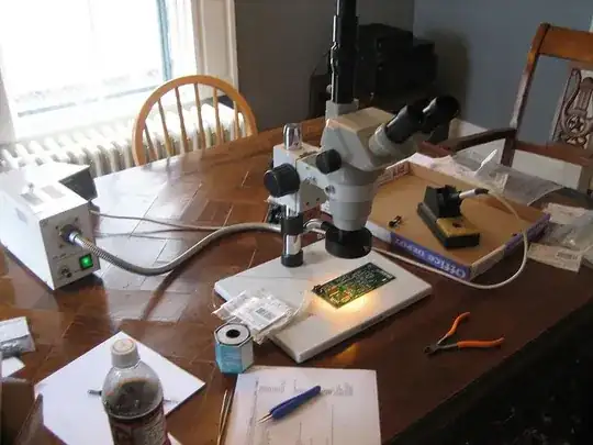
Here's my setup.

microscope on dining room table

This isn't to say that you shouldn't use an oven-- I haven't tried that; it might be better. Seems a little bit like all your eggs in one basket, but I guess you could always rework parts in either case.

pingswept
  • 12,581
  • 4
  • 46
  • 64
  • 1
    Unfortunately I don't have 2 hours to spend per board. I want to sell these for about $70 and $45 of that is PCB+component cost so $25 for 2 hours painstaking soldering isn't worth it. I will probably do this for prototypes though, but not for production. Thanks for the ideas. – Thomas O Oct 19 '10 at 22:18
  • 2
    Ah, I see. For production, doing it by hand would be insane. – pingswept Oct 19 '10 at 22:20
  • honestly which ever way you solder your probably spending a large chunk of time placing parts. Especially when it comes to the passives, the vast majority of the time is spent placing the part on the correct pad, the actual soldering takes a couple seconds. – Mark Oct 19 '10 at 22:22
  • That's a good point Mark. I have to locate components (as there are many different values used on the board), place them, apply paste and reflow. It could get tedious, which is why I'm considering outsourcing this to a manufacturer, but it's only worth it for higher quantities (~50 or so.) – Thomas O Oct 19 '10 at 22:25
  • 4
    When i have to assemble prototypes what i do is print off the silk screen layer. Get a bunch of different color markers, one for each value, and color the the foot print on the printed off silk screen. So all 0.1uF caps gets blue, etc. Saves you a lot of time staring at a spreadsheet of part numbers and values. – Mark Oct 19 '10 at 22:34
  • Good idea. As there are lots of similar values this would work quite well. – Thomas O Oct 19 '10 at 22:36
  • Nice pic. What model scope is that? – ThomasMcLeod Nov 17 '11 at 01:40
  • The base says "Amscope" on it, but it came from Ebay for cheap. I suspect it's a Chinese clone of something made by Amscope. Crappy workmanship, no documentation, and the USB camera drivers were terrible, but it works for soldering. The light source says XD-301 on it, but I think it's of similar provenance. – pingswept Nov 18 '11 at 13:42
6

At my previous work place, the guys would kit all the SMT components into little trays and then do small batches using solder paste and place all the passive resistors and capacitors, then using a handheld hot air soldering iron go over each component briefly until it "wiggled" into place and the solder reflows.

Next phase was for the semiconductors (transistors and mosfets and the like) followed by integrated circuits.

Final stage was handsoldering the larger connectors and through hole components.

Spending the time to kit and prepare good assembly drawings (hand colour coded to match the bins of the parts) it meant placing all the passives went quickly as did the soldering. This method will help speed up small one man batch production, at the expense of setup time.

smashtastic
  • 3,336
  • 21
  • 31
3

How many do you intend to build? Have you considered getting a quote from some contract manufactures? If you are building enough of them, a robot is going to make it cheaper than placing by hand. Although you will have up front tooling to produce a solder paste stencil and engineering or setup costs to consider.

Clint Lawrence
  • 2,526
  • 17
  • 13
  • many software packages will produce pick and place instructions automatically with the gerber and there is no 'tooling' involved. If they have to produce the pick and place instructions you may pay a setup fee but after that loading the reels on the machine is usually included in the run cost. – Mark Oct 20 '10 at 03:25
  • The tooling I was referring to is for a solder past mask. Even if you provide a pick and place most times sent PO for manufacturing there has been a 'set up' free or 'engineering' fee. Whether it is listed separately or built into the unit cost you still have pay it. – Clint Lawrence Oct 20 '10 at 06:44
  • I am using gEDA PCB and I think it produces a CNC pick and place output. – Thomas O Oct 20 '10 at 12:12