0

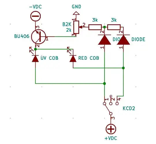
I have the following current adjustment circuit, VDC is 32V. I want to be able to switch between two COB LEDs and adjust the current however the current should be much lower than it is in practice (it's 800mA on red when it should be a few hundred less) and completely detaching the potentiometer from the base of the transistor changes nothing.

When the Red COB is activated the intent is that there should be 3k ohms more resistance than if the UV were activated because they need different currents to produce similar brightnesses.

current adjustment circuit with dual LEDs

My old circuit was the following and worked fine but I hadn't yet tried to add switching between two LEDs: current adjustment circuit with single LED
0x777C
  • 145
  • 6
  • 1
    What's the relationship between -VDC, GND, and +VDC? – W5VO Dec 13 '20 at 23:03
  • What are the relationships among +VDC, -VDC, and GND? – AnalogKid Dec 13 '20 at 23:06
  • They all go into my power supply which I set to 32V – 0x777C Dec 13 '20 at 23:07
  • That's a very strange wiring for teh potentiometer. Did you mean to connect the resistors to the top (pin 3) and the wiper to the base? Also, what's the actual relationship between -VDC, GND, and +VDC? If +VDC = 32V and -VDC = 0, what voltage is GND? –  Dec 13 '20 at 23:21
  • 3
    Your schematic is upside down. Convention is to have positive on top and current flow from top to bottom. Your ground connections should be pointing to, ehm, ground, not into the sky. See https://electronics.stackexchange.com/questions/28251/rules-and-guidelines-for-drawing-good-schematics if you're interested in learning. – Transistor Dec 13 '20 at 23:27
  • Your logic diagram is illogical ! Even the Chinese know how to draw proper logic diagrams. Define LED Vf, If first – Tony Stewart EE75 Dec 13 '20 at 23:32
  • 1
    If that's really a "UV" LED and you're running it at hundreds of mA, I hope you are wearing eye protection when you are looking at it. – Kyle B Dec 13 '20 at 23:45
  • 1
    @TonyStewartSunnyskyguyEE75 seriously, a lot of the most amazing researchers I've met are Chinese - I'm going to call your comment there a bit racist. That's not cool, actually. – Marcus Müller Dec 13 '20 at 23:52
  • @KyleB Yeah it's UVA at 700mA, the red is 600mA, I wear welding goggles unless I'm sure it's not gonna jump high (the circuit should keep it low enough that it isn't a hazard) – 0x777C Dec 13 '20 at 23:55
  • https://tinyurl.com/y2ppumnp. Adjust as required and use heat sink – Tony Stewart EE75 Dec 14 '20 at 00:01
  • 1
    @TonyStewartSunnyskyguyEE75 it's brilliant, wish I'd thought of it ;) – Kyle B Dec 14 '20 at 00:02
  • @MarcusMüller you misread. I have the utmost respect for Chinese Eng. whose linguistic challenges are greater. Yet master the art of logic diagrams. It’s the OP who is illogical – Tony Stewart EE75 Dec 14 '20 at 00:03
  • Always state assumptions before any design for all components and outputs. Vf, If, Pmax, Rja – Tony Stewart EE75 Dec 14 '20 at 00:13
  • you presented upside down schematic diagrams ..... please use the schematic diagram orientation convention ... Vcc at top, GND at bottom, input at left, output at right ... it is ok to reverse input and output if your language uses right to left writing – jsotola Dec 14 '20 at 00:44

2 Answers2

0

Your circuit can't work well. It's "open loop", meaning the input (your control) has no knowledge of what the output is doing. You need feedback for this to work well. (Well, it has a little feedback, but not very strong) It won't hold a constant current very well and it certainly won't be repeatable w/o tweaking if you're making more than one.

To feed your brain a little, you might try working with something simple like this: enter image description here

The idea here is you set R sense such that there's 0.7V across it when you're driving the amount of current you want. R load is your LED. So that's the 'feedback' here... Q2 throttles Q1's base current to ensure a constant voltage on R sense. It does this because the voltage on R sense has to be same as Q2's base-emitter voltage (~0.7V)

i.e. If you want 200mA, you would set Rsense = 0.7/0.2 = 3.5 ohms

Kyle B
  • 4,558
  • 10
  • 29
  • I'm not sure how this would tie into my existing circuit, would I have to do this once for each LED I want? At the moment I'm not too worried about having it hold a constant current, just being good enough and simple since I'm very new to electronics – 0x777C Dec 14 '20 at 00:17
  • @Faissaloo See [my discussion](https://electronics.stackexchange.com/a/481317/38098) on designing these. You could consider switching out the Rbias resistor only when switching from one LED to the other one, but that might require a multipole switch. – jonk Dec 14 '20 at 00:52
0

So it turns out that this circuit - when run in reverse, if the LEDs are also in reverse - will produce this result. So yeah, check your polarities.

0x777C
  • 145
  • 6