Your questions:
Q1: Is there a way to properly fix this circuit?
Q2: Or is it simply wrong by design?
Short answers:
A1 = Yes there is. See detailed answer, with 4 Checks/Changes and 2 Tips.
A2 = No, the circuit is not ‘wrong by design’, but needs to be calculated properly and are ways to improve its performance. Then you proto-board it too and you get something that works as intended
Detailed answers:
A1: Yes there are ways you can ‘fix’ it, if you accept a not-so-defined knee from “constant” current to “constant” voltage.
Between quotes, because is not really constant, but would work ok.
I already built some circuits like that, obviously changing values and components. But in terms of topology/configuration, they are quite similar.
I suggest a few changes:
#1 Upgrade Q1.
Q1 = 2N2222 is borderline adequate, it will “fry” due to power dissipation. Assume as worst case, V_in = 8V and dead batteries (0V). In this case Power = 8V x 120mA = 960mW.
If you use a BD135 or MJE340 assuming HFE > 30, or in a better TO-220 as TIP31 or even a TIP110 Darlington with HFE = 2500, you have several design BJT options that will dissipate 1W without heatsink.
Please observe that using a Darlington, it may be necessary to raise V_in.
#2 Review & Change R1.
Base current resistor, we could think of using
R1 = ((8 - 0 - Vbe) / 0.120) * (HFE_min / 3).
R1_BD135 = ~620R (commercial).
R1_TIP110 = ~47K.
Current in R1 is important because will drive CC LED:
However, as we wish i_LED ~= 10mA, by inspection we could see R1 is far from the determined values FDTE to polarization requirements of Q1. Recalculating by LED current.
In this case, for V_in = 8V, delta_V_NPN+LED+Bat = 5.8V.
R1 = (V_in - delta_V)/i_LED = 220.
R1 = 220R.
#3 - Review R2 & D3.
Using a LED_RED or Green, with V_f ~=2.0V,
V_R2 = (2.0 - Vbe)
R2 = V_R2/i_bat = ((2.0-0.7)/0.12) = 10R8.
R2 = 10R.
D3 = RED(new) or GREEN.
#4 Check ZenerDiode D1 and R3.
Zener Diode BZX55C in Vz = 2.7V, has an equivalent resistance between 85R (@ 5mA) and 600R (@ 1mA).
R3 voltage at 0.7V will make Q3 conduct; assuming Zener current = 5mA, we expect Vz ~= 2.7V.
So say, i_D1 = 2mA and for that, R3 = 0.7/0.005.
R3 = 150R.
Tip #1: R3 and V_out fine-tuning.
Curiously, Vbe_Q2 and Vf_D2 are not much different, so it is expected that
V_out ~= Vzener_D1.
A trick to fine-tune the Output voltage would be to change R3 in such a way that current would swing from 2mA and 30mA, which would increase the Vz by tenths of volts around the nominal 2V7.
Using R3 = 22R (fixed) + 330R (trimpot) would be a first guess.
Tip #2: Improving Voltage stability.
If you wish to get a very sharp knee with really Flat plateau for the Constant Voltage part, Zener is not the best option, as it varies the impedance much more than an “integrated Zener” as the TL-431. Another point is related to Thermal drift, which a 2V7 Zener is not the most precise if it is left close to the power transistor getting hot.
Don’t get me wrong, the Zener circuit will work as a Voltage reference, and even can be tricked (as above) because it has a comparative large impedance at a given operating point; but you can use other references too.
So, if you replace the Zener by a TL431 and use Datasheet’s Figure 10-3 or 10-5 or 10-6, it works beautifully.
Just put an 4K7 in parallel with your D4 and replace Q1, D1 and R3 by the TL431 and its voltage divider. Oh, and leave the previous C.C. Circuit as it is.
A2: So, can work and is not ‘wrong by design’. It just need some recalculations, but the circuit works.
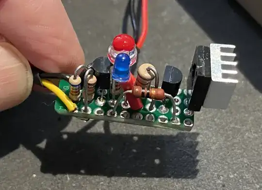
That is exactly what I have done, for a friend of mine that needed a 5 cell NiCd charger. I made one running at V_out = 6.88V & i_cc = 140mA.
See the assembly for that, using:
- Vref = TL431 + 12K & 6K8 (V_divider)
- NPN (MJE13003+2N3904)= Darlington parts from C.F.Lamp.
- Blue LED for D3 (compensate using Darlington).
- Any LED (white) as D4; too bright, ‘painted’ as RED: nail enamel used for that.
- My R1 = 820R, as I work with V_in = 12V.
- I decided to not use that output diode (your D2) as the back-voltage is not high to cause damages to the circuit and it is being used to charge a toy, so it is just connected when another recharging is needed. If you don’t feel this as adequate for you, maintain the “D2” and comped paste that in the TL’s voltage divider.
CC-CV Charger - Update with Test Data
Using the charger from the Picture, I tested it using 5 AAA advertised as 800mAh but tested individually (La Crosse smart charger) and showed actual 450-500 mAh. Battery pack (5x AAA) was fully and deeply discharged, using initially a 5R6 and then a 10R power resistor. Recovery voltage (instantaneous and after 1 minute was tabulated too.
Then a charging was monitored measuring selected Input Voltages (Nominal V_in is 12V), V out, I_out, LED status, and Temperature @ heatsink.
The Excel spreadsheet (Made in Brazil, so using comma as decimal separator and DD/MM/YYYY) then discounts the stand-by current (last line) to estimate the actual charging current. Accumulated mAh was "integrated" by trapezoidal segments (Romberg's method) for each measured delta Time.
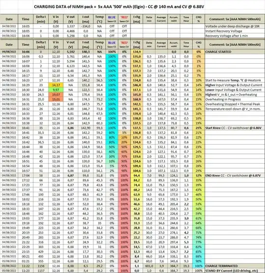
Then general curves showing some key values are plotted - consider that Nominal C = 400mAh and i_cc = 140 mA, charging rate is about C/3:
Summary and conclusions for this CC-CV Charger at C/3
Using a charger that limits CC to C/3 (C = Capacity), and CV set at 1.38V/cell:
- 25% C occurs at CC-CV switch-over (seen in LEDs).
- 50% C is achieved at 2 Hours mark.
- 80% C is reached in 6 Hours.
- 90% C is reached in 9H.
- 95% C is reached in 16H.
- 100% C is reached in 20H, with "final" charging current of 1 mA.


