7

I'm designing a project that is going to work on a flying quadcopter. It features an ATmega328P MCU in the main 5V circuit, and is powered by a small (<500 mAh) 1-cell LiPo battery. I want to provide low-voltage cutoff mechanism to protect the battery. Currently I'm considering the three options:

  1. Just let the main MCU to monitor the battery voltage, using VCC as reference. VCC is usually 5.1 V, but to be sure I will also need to measure own VCC.

    Pros: no additional circuitry. Can signal cutoff reason using a LED. Configurable cutoff voltage. Soft cutoff.

    Cons: in case of malfunctioning of the main MCU (software bug) the battery voltage may be left unobserved under a high load. Complicates software. Requires powering the 5V network.

  2. Use a Reset Monitor like MAX809. Power-down current is 0.5 μA.

    Pros: highly reliable.

    Cons: no signalling. Not easily configurable. Hard cutoff only. Additional circuitry (voltage divider).

  3. Use an intermediate MCU like ATtiny25/45/85. It is tiny but can measure own VCC. Power-down current is 2 μA.

    Pros: signalling. Configurable. Easy to test. Measures voltage before powering other things. Soft cutoff (can signal the main MCU that it's a time to gather stones).

    Cons: requires additional (but very simple) software. Weight (1g?)

Option #3 is illustrated here:

Option #3

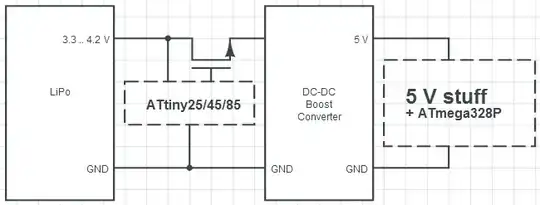
I'm thinking of going with option #3. Does it make sense?

Chetan Bhargava
  • 4,612
  • 5
  • 27
  • 40
Goodrone
  • 211
  • 1
  • 5

3 Answers3

3

I'd do #1
or #1 + #2. The main controller would be the primary battery monitor. If something goes awry with the main controller, the analog reset monitor would be the backup.

#3 makes sense if you think that later you might add more functionality to the dedicated battery monitoring controller.

Nick Alexeev
  • 37,739
  • 17
  • 97
  • 230
1

We do #1 and #2, working thus:

  • Board is powered from 24v, so our 3v3 supply is regulated down from that. If the 24v goes down we have a long time (in CPU cycles) to see that happen using a voltage-divider and ADC pin on the micro, and make a note of it by setting a bit or whatever you want to do.
  • Reset monitor catches the "hard cutoff" of the 3v3 rail having a wobble, going down, spiking, etc. and forces a hard reset (grabs the micro /RESET pin and holds it low until it's really happy with the 3v3 line) which prevents the micro from missing a problem due to high load (although that's what hardware watchdogs are for).

A point worth thinking about is how, using #1, you can actually store the reason in a way that survives the reset/power-loss and doesn't risk corrupting something by loss of power half-way through a flash-write cycle or something. We have plenty of time as our power source has a long way to drop (20.7v) before the 3v3 line dies, but in your application you may not.

John U
  • 7,041
  • 2
  • 21
  • 34
0

Try this circuit instead, for complete independence on any MCU (I can't upload an image, so I'll describe the circuit):

1 Zener diode, 5 resistors, 1 NPN transistor and one PMOS. They can be SMD or TH.

The Zener diode acts as the voltage setter, the NPN keeps the PMOS conducting in normal operation and the resistors act as current limiting and bias providers. If the input voltage falls under the Zener threshold (a little higher actually), the NPN stops conducting and the PMOS stops supplying power to the load.

Connect the components like this: Supply line to zener, arrow pointing to the positive voltage, then a resistor in series (e.g. 1k) to ground. Take the voltage from the mid-point and feed a voltage divider (e.g. 5k-50k). Take the voltage from the mid-point of the voltage divider and connect it to NPN (e.g. BC817-40) base pin. NPN "arrow" goes to GND, collector goes to a resistor (e.g. 1k). Connect the end of this resistor to the gate of the PMOS (e.g. IRF9130). A 50k resistor should be connected between the gate and the positive rail, to make sure the PMOS does not conduct when not needed (and discharges the gate capacitance, avoiding linear turn-off). Connect the source of the PMOS to the positive rail and the drain to the load positive terminal. And you have a simple UVL circuit.

A zener diode with a voltage close to where you would like the Under voltage Lockout circuit to start working is required and this is what acts as the "switch". Simulating or building the circuit might help in understanding the advantages and disadvantages: it draws a very small current (zener diode leakage + other leakages) when off. I got 0.6mA in simulations.

The above values were chosen for a 10V battery pack (LiFe) and they work great for cutting off the battery under 8.6V. For different voltages, use different Zeners and maybe also smaller/bigger resistors in the first 3 places.

The schematic can be doubled and reversed for a +/- supply configuration, if required.

I hope this helps.

dgrmkrp
  • 61
  • 1
  • 7
  • 1
    You can upload a picture to a free image sharing server and share a link to it. –  Jan 10 '13 at 14:23