-2

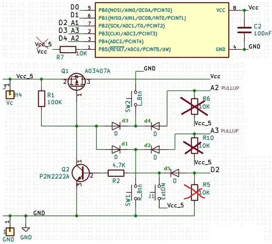
I have a project to control 2 LEDs with ATTiny13A with 2 buttons.

The goal is: when is not in use, the consumption has to be zero(close enough to zero).

To accomplish this task I decided to make a software latching ON/OFF button (2btns[SW1 and SW2] either one of them should start the power for the controller.) I end up with this schematic, but surprisingly for this simple task I have to put a lot of elements to make it work. I am new in electronics, and I am wondering if I can make it simplier - I mean not just remove some of the elements, but redesign it to use less elements.

A1 and A3 are INPUTS for the status of the 2 buttons, D2 is OUTPUT to latch the power to the controller. D0 and D1 are the PWM OUTPUTS to power the 2 LEDs.

The J1 button is optional (but needs to be there) for remote power ON. The power is 3x1.5V batteries = 4.5V.

The other question is: how efficient is for the consumption-when is OFF there is consumption of 0.03uA which is practically 0, but when is ON. It needs to consume as little as possible

EDIT: I should have mentioned that I cannot use the sleep mode. I simplified the task the ATtiny is doing so as not to complicate the question. There are so many things to be programed that I have no more space for extra programming to put it in sleep mode and even more to program interrupts to wake it up. So let say the program limit of the MCU is reached and there is no more space for a software solution - need to be done through hardware (excluding the ATTiny13A- I can not change it has to be ATTiny13A.)

EDIT2: Please comment if you have any suggestions for the design of the schematic. I do not ask for solution or the way how to do it...i asked how to improve the design of the schematic-it is just electronic's question for somebody good with electronic.
enter image description here

Serial
  • 7
  • 4
  • Comments are not for extended discussion; this conversation has been [moved to chat](https://chat.stackexchange.com/rooms/116853/discussion-on-question-by-serial-looking-for-better-design). – Voltage Spike Dec 01 '20 at 15:26
  • 1
    Could you please explain what is taking place in the firmware that is occupying so much of the memory? From my understanding, there aren't any other functions taking place other than reading the pushbutton inputs and generating PWM outputs for the LEDs. Are there complex / lengthy patterns you're creating? We're just trying to understand what led you to your constraints. – Adam Lawrence Dec 01 '20 at 15:44
  • @Adam Lawrence I do not understand why it is so important for you but...It is a part from a bigger device - i have to read CO2 sensor trough a serial communication and accordingly change 2 PWM outputs signals(similar to the brightens of LEDs). I did this before with Tiny85. I wrote library for the communication in assembler(takes only 48bytes) and uses 1pin for both Rx & Tx. I need just to readjust the delays for 9MHz[currently is for 16Mhz]. I have 9 bytes buffer, CRC-calc, and sending an output signal to D0 or D1. On plus - they ask to be with power cut. It will be their way. No choice! – Serial Dec 01 '20 at 17:01

2 Answers2

6

What you actually need: minimal schematic

Why?

The Attiny13 can power itself down, and wake up on any of the input pins changing.

In power down mode, it uses practically no current, see Table 18-1, p. 118 of the datasheet. The 0.15 µA are probably negligible compared to how much your battery discharges itself. For example, if your battery has 100 mAh of capacity, then it would take roughly 115 years to empty it through the sleep mode.

You don't need any resistors to pull the pushbuttons up – the attiny has built-in pull-ups.

So, you really need nothing but the switches.


Incorporating your edit:

There is so many things to be programed and i have no more space for extra programming to put it in sleep mode and even more to program interrupts to wake it up.

I call "Nonsense" on that. If that's the case, instead of spending money and complexity on external stuff, get a MCU with more memory. This really is no excuse. Also, programming these pins to be wakeup pins should take about 4 bytes, putting it to sleep is a single byte. I doubt your system is that full and you have no way to optimize.

Also, you're already occupying all output pins with your overly complex solution, so what else does the MCU have to do? It has no way to "talk" to the outside world. You're not really telling us why you think this is no option.

excluding the ATTiny13A-i can not change it has to be ATTiny13A

Then learn to optimize your software, write assembler, add an external memory for more program space, but really, your complex analog circuitry safes you nil on actual power. And the restriction that you can only use an Attiny13A sounds absolutely artificial, too.

Marcus Müller
  • 88,280
  • 5
  • 131
  • 237
  • Thank You for the effort. Nonsense is ONLY for you! Sorry-your solution is good, but not for my case. Your way of thinking is too straight forward....the decision of which kind of MCU will be used is already made, and it is not mine. Putting it in a sleep mode will take more then 1 byte if you want to wake it up and remember what it was doing before the sleep. I use ALL of the IO pins....what about the PB5(RESET-pin)-i can perfectly make 2-WAY serial communication with just 1 pin[if you do not know how i will be happy to teach you] ...I see that you have some knowledge,but not in this case – Serial Nov 29 '20 at 21:19
  • Please see EDIT2 section. – Serial Nov 29 '20 at 21:28
  • 3
    the EDIT2 poses no helpful addition to your question, sadly. You don't explain the actual constraints of your application, so we can't help you with your design more than I did. Also, no, it really doesn't take more than one byte. Page 5 of the datasheet: The power-down mode saves all registers, and you work directly from where you put it to sleep after the wakeup has been handled. Also, "the hardware decision has been made without consulting the hardware person" makes no sense. Well, then "someone" will have to change their decision because they decided too early. Not your fault. – Marcus Müller Nov 29 '20 at 21:33
-3

For the rest of the community who may find this approach not too bad...

  1. So far we removed R6 and R10 and use the internal PULLUPS on A2 and A3. I am not sure if i do the same with R7 will be OK... No! I need to put R7:Does ATtiny RESET pin need a resistor?

  2. The R7 has to go to Vcc not Vcc_5.

  3. No need of R5 too! enter image description here

Serial
  • 7
  • 4