4

I originally asked a question about this picture: Circuit LTspice implementation not working

Enter image description here

I am trying to understand this MOSFET circuit in terms of how it becomes a non-linear Chua's diode through LTspice. However, ultimately I realised I don't understand this at all.

How does this actually all work? The theory, etc. would be great, or just a step-by-step explanation.

The source of this: https://books.google.co.uk/books?id=Tve6CgAAQBAJ&pg=PA17&lpg=PA17&dq=mosfet+in+chua+circuit&source=bl&ots=aOxjnewukF&sig=ACfU3U01aTtquge_KsePIF1yGUP0IbRDBw&hl=en&sa=X&ved=2ahUKEwjD2_CrvvvsAhWFs3EKHdxWCBg4HhDoATADegQIAxAC#v=onepage&q=mosfet%20in%20chua%20circuit&f=false

Original source: http://engineering.nyu.edu/mechatronics/Control_Lab/bck/VKapila/Chaotic%20Ref/Porfiri's/Biblio/Donoghue.pdf

It is an implementation of a chaos circuit inspired by Leon O. Chua.

Peter Mortensen
  • 1,676
  • 3
  • 17
  • 23
kepsek
  • 75
  • 11
  • What is the original source for this circuit? I mean, why would anybody try and derive how it works if there isn't some evidence that it is supposed to do something useful or interesting? – Andy aka Nov 25 '20 at 12:44
  • @Andyaka My apologies, I have added all the sources. The link to my other question will also have more information. – kepsek Nov 25 '20 at 12:51
  • +1 for its wow factor .What would happen if you put inductance in series with the battery? . – Autistic Nov 26 '20 at 02:10
  • You may have rushed with the bounty. The circuit has been the subject of a lot of research. The [Wikipedia page](https://en.wikipedia.org/wiki/Chua's_circuit) has a nice article, in particular its references. #3, #4, and #5, in particular, are freely available and dedicated papers. They might be heavy on the math, but that only tells you that, if you expect a nice, simple explanation, then Bimpelrekkie's answer will do (even if it's more oriented towards general oscillators); otherwise you're in for quite a trip. – a concerned citizen Nov 27 '20 at 17:35

3 Answers3

4

The left part of the circuit:

enter image description here

is an LC parallel circuit. If you would charge C2 to a certain voltage, then disconnect the voltage source and measure at VC2 you would see a damped sinewave. The sinewave will die out due to the loss introduced by R2.

enter image description here

If we could compensate for the losses introduced by R2 (and other losses as well) then we would have an oscillator and then the sinewave would not die out.

The way to do that is by adding a resistor with a negative value in parallel to the LC parallel circuit. The right part of the circuit with the MOSFETs and the battery behaves somewhat like that negative resistor. At least for small signals it does.

To prove that this circuit actually behaves as a negative resistor for small signals you would need to analyze it using small signal analysis.

Note that the battery needs to be there to provide power to the MOSFETs so that they can be biased and also to make the circuit able to deliver power to the other circuit.

An (ideal) negative resistor does not dissipate power (like a normal, positive resistor does) instead it delivers power!

enter image description here

The negative resistor isn't fully in parallel with the LC parallel circuit, instead R1 and C3 are used to "decouple" the circuit a bit from eachother. That way the LC circuit is influenced less by the behavior of the negative resistor part of the circuit.

The negative resistor only works properly for small signals, for larger signals the negative resistor's value will increase making it have less influence on the LC circuit. This is actually good because this will make the circuit oscillate at a certain amplitude that remains stable.

To learn more about LC oscillators, maybe this will help.

Bimpelrekkie
  • 80,139
  • 2
  • 93
  • 183
  • There's a little bit more in this case: it needs to have its slope, or inflexion points, such that while the LC is decaying, it reaches a part of the negative resistance where the oscillations rise again, and a range of values for the elements such that the upper region on the slope causes the oscillations to die out, and these trigger points never fall in the same place, twice. That's what gives its chaotic behaviour. – a concerned citizen Nov 25 '20 at 15:08
3

The circuit was, and is the subject of some serious studies, by people far more knowledgeable. So a simple explanation will never cover everything, and may not even cover the basics.

But, as mentioned in the linked answer, this has its roots in the Lorenz chaotic circuit. But while that one implied the use of multipliers (analog, at the time) Chua managed to make this one with simple components, thus simple to implement. The only "special function" used was a negative resistance. Such a resistance, as Bimpelrekkie's answer shows, is used frequently in oscillators, but in this case, being an oscillator is not enough: it needs to oscillate in a quasi-random way. I say "quasi", because some studies showed that it is possible to have a special 3D geometry, named the horseshoe map, in which depending on the starting point you can generate a periodic trajectory which may seem chaotic.

Whether that is the case, or not, the circuit needs a special kind of negative resistance, such that when the oscillations start, they are not maintained at a fixed level, but are perturbed, causing a break in the pattern of oscillations, while not cancelling them (completely). The conceptual schematic is this (from Wikipedia):

Chua

The RLC side of the circuit is a basic passive network. As the other answer shows, it decays naturally as a response to an external stimulus. The conductance for the negative resistance has three possible ranges of values:

  1. G<0 => oscillator
  2. G>0 => exponentially decaying sine
  3. G=0 => the slightest perturbation causes the circuit to become one of the two above

That is the equilibrium point. From that point, there are only two paths: oscillations, or damping. These two are not enough for a chaotic circuit, so a third path needs to be introduced. It's similar to a binary system: it can be harmonic, or it diverges; a three-body problem is chaotic (apparently almost solved recently), it has three degrees of freedom. Chua's solution was a double-slope negative resistance, which had inflexion points.

In the clumsy comment I tried to say how these inflexion points influence the oscillations. Re-reading it now it doesn't make much sense, so I'll try to say more here. The single slope conductance is replaced by a piecewise linear function. What happens is now there are two slopes, and each slope has its characteristics. When G>0, irrespective of the slope, the circuit is dissipative, it decays to zero. When G=0, it's the same point as in 3), above. But when G<0, now there are two slopes, and each slope can influence the oscillations, but there can be solutions where the negative slope causes oscillations to appear. But when they reach the point of G=0, they either cross the region in the dissipative region, or the oscillations rise until they reach the negative inflexion point. Depending on the second slope, that can either emplify further the oscillations, or attenuate them (but not dampen). If the second slope is also negative, it will only amplify further the oscillations, at a different rate. If it's positive, it will damp them. Depending on the settings, this can cause a quasi-periodic state of oscillations, back and forth.

It's more complicated than this because it involves solving the differential equations and using the eigenvalues for the equilibrium point, and I'm not sure how my English helps here, but if you want more details, the citations from the Wikipedia page, #1,#3, #4, and #5 are freely available and full of math.

For the sake of a simple example, here is the same circuit with the very simple implementation of an RLC circuit and a piecewise nonlinear resistor:

test

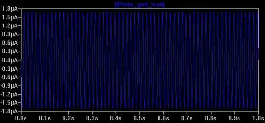
G1 has a simple, random valued, piecewise linear function, where from ±10 V to ±3 V it has a positive slope, and a negative one in-between. R1 was a trial-and-error, but as you can see, the value is very sensitive if it needs two decimals. So, the proof is that the circuit does show chaotic behaviour, even for a randomly chosen negative resistance.

What you have linked in your answer is an attempt to make the transfer function smooth, instead of piecewise. It may as well be a whim (though I doubt it is). This is the difference between the transfer functions of the test above and the circuit in your links:

diff

As you can see, the only difference is the smoothness, since both are a combination of positive and negative slopes.

a concerned citizen
  • 21,167
  • 1
  • 20
  • 40
  • I've looked into the CMOS inverters but do not understand the connections here, how does the orientation, i.e two symmetrical CMOS pair inverters, create negative resistance? – kepsek Nov 28 '20 at 19:33
  • @kepsek It's a variant of [this](https://mipro-proceedings.com/sites/mipro-proceedings.com/files/upload/meet/meet_019.pdf). It boils down to one inverter being driven by the other, each influencing the transfer function of the other. If you look closely, the output of one inverter is the input of the other, and vice-versa. One pin of the negative resistance is the input of the 1st and the output of the 2nd, and the other pin is the input f the 2nd and the output of the 1st. – a concerned citizen Nov 28 '20 at 22:54
0

If the FETs are very strong, the circuit will move into a stable state, and remain there.

Thus the use of weak FET is crucial.

Weak FETs and positive feedback, as you have here in the back-to-back inverter, is a standard speedup method for low-power circuitry that need to enhance the "squareness".

Peter Mortensen
  • 1,676
  • 3
  • 17
  • 23
analogsystemsrf
  • 33,703
  • 2
  • 18
  • 46