3

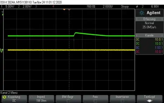
I am trying to detect an IR signal with a photodiode to connect it to my STM32F411 and use it as a trigger signal. The signal I send are two pulses at 500 kHz which looks like this:

enter image description here

I am using a transimpedance amplifier and a bandpass filter to get rid of parasitic signals of the photodiode.

enter image description here

I can detect a rising edge on the receiver side, but it is not fast enough. How can I improve the curcuit to have the same signal I send? That means two pulses with a frequency of 500 kHz.

enter image description here

The measurement was right after the amplifier on V1. So this signal I receive will not pass my bandpass filter. It looks like my circuit is way too slow to reproduce the two amplitudes from the sender.


After receiving answers explaining why the TL074 is a poor choice:

I replaced the TL074CN with an MCP6292 which has the right DC specification. Furthermore I connected the photodiode to ground instead of connecting it directly to VDD.

enter image description here

The rising edge looks pretty good, but now the falling edge isn't fast enough.

enter image description here

Getting closer but not good enough to detect it with my microcontroller.


As recommendet i lowered the Transistor to 10k and removed the capacitor. Now i have a new behaviour, it depends on the distance from my IR sender to the photodiode. If the sender is 10cm away fron the photodiode, the graph looks like this:

enter image description here

If the sender moves away from the diode, the two pulses appear.

enter image description here enter image description here

After 1m the green signal dissapears. How can i increase the range, by using a better photodiode or a different amplification? And how i get rid of the overload/overamplification?

  • How reliable is your LED drive circuit? LEDs won't turn on/off the same as your current signal because they take time too. (Look up carrier sweep). – DKNguyen Nov 24 '20 at 15:17
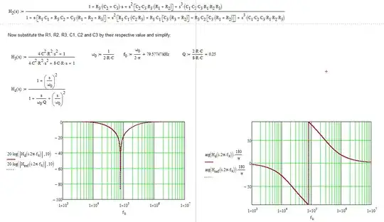
  • The 100kOhm resistor and a 20pF capacitor form a lowpass filter with an 80 kHz cutoff. Are you trying to resolve the 500 kHz signal? Or just see that a pulse arrived? If you want to resolve the individual pulses, you will need a much faster opamp, and to put the reverse bias back into the circuit. – user1850479 Nov 24 '20 at 17:40
  • @Walter are you finished with this now - did you try lowering the resistor value in the feedback circuit? – Andy aka Nov 25 '20 at 09:48
  • @Andyaka yes, i attached the result in my question – Walter Nazarenus Nov 25 '20 at 13:07
  • But you never said whether your result is acceptable or which one it is. I suggested you reduce the resistor and I have no idea what you did or whether what you now have is acceptable. – Andy aka Nov 25 '20 at 13:18
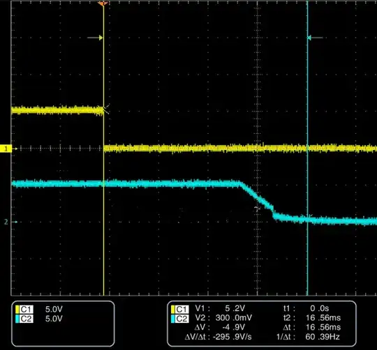
  • The result i want to have should look like in the last picture. Until now it just works in one sepcific distance from the sender to the receiver. like i said, i removed the capacitor and replaced the resistor with an 10k resistor – Walter Nazarenus Nov 25 '20 at 13:22
  • If you expect the signal output to remain stable with varying distance this won't happen without significant redesign so, I ask again, has your question been answered? – Andy aka Nov 25 '20 at 20:02

2 Answers2

7

Read the following data sheet extract from the TL074 and see why your circuit is ineffective: -

enter image description here

enter image description here

So, if you fixed the supply rails the next problem will be that your output signal will be negative relative to 0 volts; this is because photocurrent flows into the cathode and out from the anode thus forcing the op-amp output to go negative to maintain -Vin at 0 volts. So, your circuit is inverting and producing a negative output (well it would do if you applied a negative voltage rail instead of 0 volts).

I am trying to detect an IR signal with a photodiode to connect it to my STM32F411

Your input pin won't handle negative inputs so either add another inverting stage or turn your photodiode around and bias it from -3.3 volts. However, you'll still need a negative rail on your op-amp if you turn the PD around because the TL074 can't handle input signals close to the negative supply rail: -

enter image description here

And the output doesn't work close to the negative rail either: -

enter image description here

You might also consider using a faster op-amp so that the output looks a bit more like the input photodiode current although this may not be necessary - only you can decide this.


Follow-up edit by OP

It looks to me like you are overdriving the photodiode with respect to the feedback resistor you have fitted. Try lowering the feedback resistor to 10 kΩ to see if you get an improvement. The overload you are creating will take several microseconds to clear so be aware of this when driving the output into the rails. Also remove the 20 pF capacitor - you might be able to get away without it at the expense of slightly more noise on the output.

Andy aka
  • 434,556
  • 28
  • 351
  • 777
3
  1. You are operating the TL074 outside its ratings. The datasheet says the minimum single sided supply is 4.5V. You are trying to use 3.3V.
  2. The input voltage range is also rather limited. I'm not familiar enough with transimpedance amplifiers to know whether that's a problem.
  3. The gain bandwidth product of the TL074 is 5.25MHz. If you need more than a gain of 10, then the TL074 can't deliver it for your 500kHz pulses.

To your updated results:

  1. I think you have too much gain. That output curve looks like overload and recovery.
  2. I think your feedback capacitor is too large. It is effectively a low pass filter. If you look at the rising edge of the output signal, it takes longer for the output to reach its final state than the input signal exists.

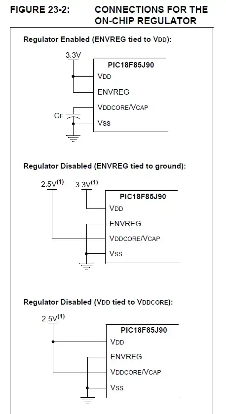
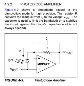
The MCP6261 datasheet gives this example photodiode circuit, and mentions that the feedback capacitor may not be needed.

enter image description here

Photodiodes are faster when used in photoconductance mode than when used in photovoltaic mode (as you seem to be doing.) Maybe your photodiode isn't fast enough for your signal when used in photovoltaic mode.

A final thought: Are you sure your transmitting LED is faithfully transmitting the two pulses?

JRE
  • 67,678
  • 8
  • 104
  • 179