I'm a student that is trying to learn hardware by building various devices, in this case a barcode reader from scratch. I bought a barcode scanning engine that has a 14 pin ZIF, pitch 0.5 mm (0.2 in) and am just trying to connect it to an arduino. I've spent hours trying to find a cable, compatible breakout board or similar tutorial to help me figure out how to proceed. I've done a fair amount with serial/PWM devices, so if I can just figure out how to physically connect the device, I shouldn't have any problems...I'm just lost on how to actually connect it???
Asked
Active
Viewed 2,587 times
2 Answers
8
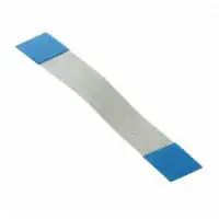
The ZIF FFC connector on the listed device is designed to be mated with a 0.5mm pitch Flat Flex Cable (FFC), also known as a flat ribbon connector or ribbon jumper. You could either solder the other end of such a cable to a break-out, or use a similar ZIF connector at the other end, on your own board.
Here is a Digikey search for 14-conductor FFCs compatible with that connector. In case that search link expires, just search DigiKey (or other similar sites) for 0.5mm FFC, the most common manufacturer seems to be Wurth Electronics.
For a relatively inexpensive breakout, look for SOP28 to DIP28 adapters with 0.5mm pitch on sites like eBay. The 14 solder pads on either half of one of these PCBs will serve as a suitable breakout for the FFC.
Anindo Ghosh
- 50,188
- 8
- 103
- 200
-
Excellent suggestion. I'll add that if the OP buys the adapter from http://www.proto-advantage.com/store/, and finds the right zif ffc connector at digikey, he can have proto-advantage order it from digikey, mount the socket on the adapter, and ship it out the door for about $25 – Scott Seidman Jan 08 '13 at 17:04
1
I'd personally call that a flat-flex rather than a ZIF.
At any rate, at minimum you will need a piece of compatible cable.
One crude option could be to try to very carefully slice the cable into individual traces, solder fine wires to them, and protect the whole assembly.
I'd be more tempted to get a matching surface mount connector for the other end of the cable. You would then need a board on which to mount it. I find it very practical and efficient to make small boards for such purposes using toner-transfer etching techniques (glossy junk mail paper, so far I've only ever personally gotten it to work with an HP brand printer - even a very cheap one - but not other brands).
You can probably buy a board with a suitable or close-enough footprint somewhere, or have one made from a board house. I choose the toner transfer method because I can go from concept to operating circuit in an hour or two, which even overnight shipping can't match. But if you don't yet have the matching cable and surface mount connector, you'll have to wait on those anyway.
Hand soldering 0.5mm pitch connectors is a skill, but an approachable one. Flux is key. And it is important to realize that you do not individually solder the pins with a tiny iron tip, instead you use a small mount of solder on a medium sized CLEAN tip and let surface tension flow it between pins and respective pads, without bridging them. You will make mistakes and cause bridges, so you'll need some extremely fine desoldering braid to clean them up. Solder just one end lightly, inspect alignment with a cheap hand loup. If it looks good solder the other end, then inspect again before soldering the pins in between.
When you design your board, having a few mm of straight trace at the connector pitch before breaking out to something wider will let you wipe solder towards and away from the pins with the iron as you are trying to get just the right amount on each joint.
Chris Stratton
- 33,282
- 3
- 43
- 89