54

Every reference I can find on transistors immediately launches into theory-heavy alphabet soup. The above seems also to be assumed knowledge for reading a datasheet. I don't care; I just want to get one to work.

I understand there's some relationship between the current/voltage applied to the base to get a particular current to flow from the collector to the emitter. Which numbers on the datasheet relate to that? If I'm only trying to operate the transistor in "switch" mode, do I really need to care what current I apply to the base or will I be fine just whacking a 1k resistor in between my logic level output and the transistor base?

Is the only difference between an NPN and a PNP transistor which way the current flows when a current is applied to the base?

Robert Atkins
  • 2,155
  • 3
  • 23
  • 37
  • 22
    You say you do not care how they work, but you want to use one. You can learn transistors by rote, but with a basic understanding they are rather easy to use(barring special cases like >100 Mhz operation) – Kortuk Oct 18 '10 at 17:00
  • 16
    you need to at least figure out the differences between BJTs and FETs. – Mark Oct 18 '10 at 20:12
  • short answers: Beta is usually called hFE and maximum base and collector currents something like Ib(max) Ic(max). Mostly you're fine: 1k lets past 1mA per volt over it. Broadly speaking, yes. Do check the long answers, they'll be useful. – XTL Oct 19 '10 at 05:57
  • 6
    @Rick_2047: that was smart posting it as a comment. You can't downvote comments ;-) – Ponkadoodle Oct 20 '10 at 04:40
  • I will post a gibberish answer, downvote that if you want to. I just don't like copy pasting things. – Rick_2047 Oct 21 '10 at 04:22
  • 7
    Learn about transistors from a book like The Art of Electronics. That starts with practical circuits and simple models, and then gets into more detail when you need it. The textbook way of teaching transistors is terrible, and makes simple things seem amazingly difficult. – endolith Mar 31 '11 at 14:53
  • 1
    suggest re-title from "I don't care how a transistor works, how do I get one to work?" to "I don't care about transistor theory, how do I get one to work?" – JustJeff Jan 29 '12 at 18:20
  • @Rick_2047 Could you update the link please? – Utku Jan 10 '16 at 12:32
  • 2
    @Kortuk I did not understand how a derailer on a bicycle works, not a transmission in a car, but my use of both is still proficient. How are transistors different? – tuskiomi Dec 15 '16 at 16:02
  • @tuskiomi - Valid point. I would think that not know that would make some parts of automotive and bicycle design challenging though. – Kortuk Dec 17 '16 at 10:11

5 Answers5

43

The base-emitter junction is like a diode. When the voltage across it (Vbe) exceeds approximately 0.65V (can be as low as 0.55V and as high as 0.9V, check the datasheet for your transistor) it begins conducting.

The current (not voltage!) through the base emitter junction is amplified by the gain of the transistor, which is known as HFE. Ic(collector current) = Ib(base current) * HFE. Remember HFE is not constant for transistors, it varies from transistor to transistor and depending on temperature, previous usage, etc., so don't rely on it for controlled amplification. For the 2N2222 it is around 160, plus or minus 30.

By applying a base-emitter voltage exceeding 0.65V to the transistor you can use it as a switch.

schematic

simulate this circuit – Schematic created using CircuitLab

(It is an NPN transistor you want. 2N3904 or 2N2222 will do.)

If you want to use an LED which is not blue or white then use a 47 ohm resistor in series with it.

When you press the switch the LED will come on.

Funkyguy
  • 3,558
  • 1
  • 21
  • 45
Thomas O
  • 31,546
  • 57
  • 182
  • 320
  • with a 2n2222, Vbe at saturation of 0.8V is not uncommon. Typical Vce at saturation is around 0.2V, so if you see more than 0.25 or so, you need more base current. – JustJeff Oct 18 '10 at 22:10
  • That's why in my circuit I demonstrated connecting to +3V. No one voltage will fit for all transistors. Some transistors conduct well as low as 0.55V, and I've seen many bipolar transistor based circuits (like oscillators) that work well down to 0.5V. – Thomas O Oct 18 '10 at 22:15
  • 4
    You should probably mention in 2nd paragraph that it's the current through the collector that is an amplification of the current through the base. I.e. `collector current = base current * HFE`. – Craig McQueen Oct 18 '10 at 22:39
  • 3
    +1 for the current comment in this answer. I feel like this was a major mistake during my learning of electronics (and not just limited to transistors). Current matters, you won't get anywhere without some electrons moving at some point. – Chris Gammell Oct 19 '10 at 18:53
  • 1
    Wait, what? You mean a transistor in "switch mode" acts NOTHING LIKE A SWITCH? I.e., it's the current applied to the base multiplied by the Hfe which governs the current south of the emitter, rather than whatever load is hanging off the emitter and the voltage across the collector and emitter? – Robert Atkins Oct 20 '10 at 17:37
  • Imagine the base-emitter junction is a diode (it is, but it's a bit more complex.) The current through the diode determines the current coming into the collector. The emitter current is the sum of the base current and collector current. In saturation, which is what this is being used as, the transistor acts as a switch and drops 0.1-0.2V. – Thomas O Oct 20 '10 at 17:44
  • 1
    ARGH! I've just worked out what I'm doing isn't working! Instead of GROUNDING the emitter and putting the load (a string of LEDs) between the positive end of the power supply and the collector, I was putting the load between the emitter and the negative of the power supply. Sometimes it's hard because you just don't know what you don't know. – Robert Atkins Oct 21 '10 at 09:13
  • Putting the load after the emitter would work but only if you could tolerate 0.7V of drop across the transistor. So if you had an LED that operated on 3V it would be no good after the emitter because the LED would only see 2.3V with a 3V supply. – Thomas O Oct 21 '10 at 12:12
  • Sorry, I'm downvoting because of the characterization of a bipolar transistor as a current amplifier, rather than as a voltage controlled current source. Current amplifier is not a useful characterization in practice or in theory. The base current in a transistor is just a flaw. The min hfe of a pn2222a varies by a factor of 3 between I_c=0.1mA and I_c=150mA. But the small signal transconductance is I_c / V_t, where I_c is the bias current and V_t is the thermal voltage. In theory, calling a bjt a current amplifier is like calling a diode a current controlled current device. – Wandering Logic Apr 22 '13 at 00:22
  • 1
    @ChrisGammell FETs get you pretty far without any gate current. – ntoskrnl Jan 05 '15 at 10:36
17

NPN (and PNP) implies BJTs. No, you do not need to understand the bipolar transistor to great depth (is an advantage, of course). Just know and use standard circuits.

Easy to follow explanations and calculations for finding resistor values (or checking that the 1 kohm resistor is OK) for the switch you have are in "Transistor Switch". Standard small signal amplifier circuits are also listed on the same page.

alt text

A more detailed explanation can be found in "Transistor as a Switch".

Peter Mortensen
  • 1,676
  • 3
  • 17
  • 23
7

Watch this cool video about transistors. It'll trick you into being interested about the alphabet soup.

You should really learn about the basic chemistry of p-type materials, n-type materials and doping. You can then visualize the potential differences and where the electrons are going to go without having to really memorize anything. Don't be lazy here. :)

Then an article like this will fill in the gaps.

Learn about the concepts behind a basic transistor/diode. Then all of the other acronyms will fall into place without any real effort on your part.

PetPaulsen
  • 2,335
  • 4
  • 22
  • 34
  • 4
    Note that the video you mentioned is pretty flawed, in that he confuses enhancement and depletion mode FETs with NPN and PNP BJTs. PNP transistors are not normally "on." – John Miles Sep 14 '11 at 17:07
6

Those answers and comments that say, "I know you don't like it but you have to learn the alphabet soup," are wrong.

I was lucky enough to come across EXACTLY the video(s) you want some time ago. It teaches you how to USE transistors without the ubiquitous lesson of how they are made in silicon.

Despite what others say, you will learn BETTER if you leave out the abc soup until you have practical knowledge. I never really understood transistors before; I'd been taught to think of them as little switches (which is very misleading, at best). Now I know enough to comfortably put them into use. Here are the videos:

What is a transistor? How does a transistor work? Part 1

What is a transistor? How does a transistor work? Part 2

Trevor
  • 69
  • 1
  • 1
4

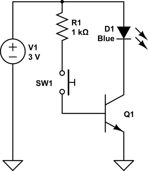
I'd propose starting step by step with something tangible. Chew on one case at a time.

You might start with the simple case of a switch and I'm sure you can find very simple examples by looking. Don't dive into an old book with CE bipolar amplifier biasing with half a dozen resistors, compensation and h parameters flown through on the first page written by someone who doesn't remember what it was like not to know all that stuff first. :)

If you look around, it should be easy to find some tutorials with BJT, JFET, MOSFET... Maybe skip P and depletion devices first as well. Mostly P (PNP) does look like a mirror image, once you have an idea how the N part works, it should be easy to relate to the P part. That way you won't get so much chance to be confused by negative voltages and currents and circuits drawn upside down (they really do all that).

Then you really need to look at the datasheet parameters like just how much current and voltage it can take safely, what's the ratio of base current (gate voltage) needed/taken for a given collector current, total power dissipation (voltage loss * current) etc.

Once you're done with switches, you might look at turning on/off only partially (amplifier, current control). All three types behave a bit differently. Then maybe see different typical circuits: regulators, current sources and mirrors, timers, logic gates, B and AB power amplifiers.

A bit of theory (multiplication, Ohm's law, diode...) is necessary, more will help you understand what's going on and predict things. But you should be able to jump in with ballpark values first. Use some cheap parts (with the datasheet, at least for the pinouts and type) and perhaps a simulator to try things out.

XTL
  • 1,223
  • 1
  • 11
  • 18