3

I have a question regarding the distortion I see at the transition of bit '0' and '1' in an FSK, I have the receiver connected to a sensing circuit at two frequencies, because my input is current limited at the sensing frequencies I would like the impedance to be as large as possible in order to get a good voltage range for sensing. I thought I might update the components with their respective parasitic resistance, because I am not sure whether the damping solely was the cause of it.

enter image description here

The response of the circuit looks something like this

enter image description here

However, when I actually test the circuit together with the receiver, I see some distortions between transitions

enter image description here

another example enter image description here

and if I run an FFT this is the result I get, offsetting the window doesn't help either, so it's not because I am slicing into part of the previous bit. enter image description here
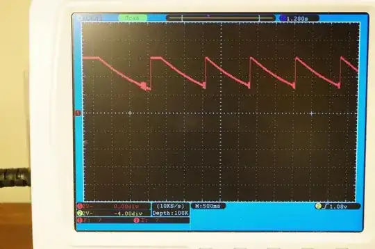
I know the frequencies are all slightly different in these cases, it's because I had to tune my circuit a bit for 24 kHz and 32 kHz, but I don't think that would have changed the behaviour I observed so I hope the problem is still valid.

Basically, if I send a series of '010101010101....' and have a sliding window of baudrate (so say for example frequency 1 is 24 kHz, frequency 2 is 32 kHz and the baudrate is 4 kHz), instead of clearly seeing a tone at frequency 1 and frequency 2 for bit 0 and 1 for each bit, I essentially see a mix of two frequencies with similar amplitudes, and there is never a clean signal.

greatly appreciate any pointer!
user3602697
  • 119
  • 6

1 Answers1

1

greatly appreciate any pointer!

It appears (and it isn't that obvious so I might be wrong) that you have an input filter circuit that is very highly tuned as per this in your question: -

enter image description here

And if that is so, then what you are seeing (when data changes the FSK frequency from 23.5 kHz to 32.2 kHz) is the tuned circuit "ringing" for far too long. I recommend that you scrap the idea of filtering without damping (the stuff that makes things like this actually work) and use.. er .. damping to prevent the extended unforced oscillations being produced when you change the excitation frequency.

You need to design a better filter system with much lower resonant peaks and damping is your friend in this respect.

Andy aka
  • 434,556
  • 28
  • 351
  • 777
  • Thanks for the pointer! I am not from the field so just have a perhaps very straight forward follow-up question, the plot you have is actually the impedance/resistance, and not the voltage/current response. Basically at these two points that impedance is very high, causing the voltage to be high and there is basically no current/power dissipation, would you expect ringing to be a severe problem in this case as well? – user3602697 Nov 19 '20 at 14:09
  • I see no damping resistors to restrict the massive resonant peaks in your circuit so.... they will produce massive resonant peaks and "ring like hell". The length of time the rigning continues for is reduced with damping as well (but there are no damping resistors ). Without damping the unforced oscillations will leak significantly into the next data symbol and, well, that's what you see in the LTSpice picture and it gradually gets worse from left to right. – Andy aka Nov 19 '20 at 14:14
  • Ah, okay, I will take a look into that, many thanks! – user3602697 Nov 19 '20 at 14:14
  • An ideal inductor, connected to an ideal capacitor, would oscillate forever. Resistance is the only thing preventing this from happening. Research "critically-damped rlc" for more info. – rdtsc Nov 19 '20 at 17:56