0

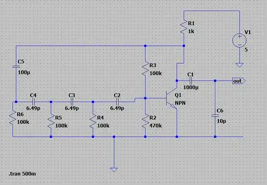
I am trying to build a phase shift RC circuit as shown below. I want the output frequency to be 100Khz at a 5V input and I want to be able to lower the output frequency as I lower the input voltage. So far I have looked into RC phase shift oscillators and used the following equations to determine my cap values. enter image description here

I verified the the DC bias point of the transistor to be operating but for some reason the oscillations don't show up. Below is my circuit built on LT spice. Any tips to help me achieve a variable RC phase shift oscillator?

enter image description here

Mitu Raj
  • 10,843
  • 6
  • 23
  • 46
electricz
  • 3
  • 1
  • 1
    First thought - connect the top of R3 directly to V1, so it is not a negative feedback path. Also, some sim programs have a startup problem with oscillator circuits. Others around here know more about that than me. – AnalogKid Nov 19 '20 at 00:23
  • 1
    C2 is not feeding 100k ohms. Instead, the base-emitter resistance is about 1.6k ohms. – Audioguru Nov 19 '20 at 00:54
  • Everything said, plus specify an actual small-signal transistor model, i.e. a 2N3904. I think I'd switch the bias scheme to use emitter degeneration, and reduce the impedances throughout by a factor of ten or even 100 (i.e., lower the resistances and increase the capacitances) – TimWescott Nov 19 '20 at 01:56
  • See [here](https://electronics.stackexchange.com/a/371292/38098) and [here](https://electronics.stackexchange.com/a/337900/38098) for a couple of somewhat related cases. – jonk Nov 19 '20 at 02:17
  • Try swapping C2 and C5. You can't change the frequency by changing the supply voltage, you'll need a different oscillator design to make it tunable. – Graham Nye Nov 19 '20 at 02:23
  • Not accurate for adjustment https://tinyurl.com/y5flh4qw – Tony Stewart EE75 Nov 19 '20 at 09:45
  • 6.5 pF??? That'll be swamped by stray capacitance unless you're a VERY careful constructor! Try 650pF and 1k (or maybe 130pF and 5.1k) keeping the time constants the same. Also, oscillations may not show up in simulation : you might want to make V1 a step (0 to 5V) to kick the thing to get it started. –  Nov 19 '20 at 12:45
  • A single Q- RC has very low Q, gain to regulate f and Vout yet my design works but cannot be VCO with Vcc . Impossible – Tony Stewart EE75 Nov 19 '20 at 15:14

1 Answers1

1

The input resistance of the bipolar is beta * reac, where reac is 1/gm. At Ic = 1mA, reac = 26 ohms. At 0.5mA, reac = 52 ohms.

Your transistor operates at about 2mA, thus reac is 13 ohms.

Scaled by beta, that produces Rin (at DC) of 100 * 13 = 1,300 ohms.

Which in parallel with the final 100K ......... produces problems of phaseshift and attenuation.

Additionally, the input capacitance is set by Miller Multiplication.

That Cin is (1 + gain). Gain is about 1Kohm Rcollector / 1/gm

or 1,000 / 13 == 80X.

With typical bipolars having Cob of 10pF, the Cin is 800pF, not at all appropriate for a 3-stage phase shifter with 7pF.

==================================================

To reduce the input capacitance (to reduce the Miller Multiplication), introduce a 2nd bipolar atop the first; bias that base to +1 volt, and bypass that (new ) base with 0.1uF because at 100,000Hz the Cob of 10pF? will easily move that base up and down. This (2nd transistor) is called Cascoding.

To improve the Rin, use the ideas suggested in the comments , inserting 10KOhm resistor in the Emitter to Ground. To work with the 100,000 ohm phase shift resistors, you need 1Megohm??? and that requires beta * 100K = 1Meg. This high value of Re requires rethinking all the biasing.

Additionally, the 20pF Cin of the original transistor (reduced from 800pF, as the cascade helps greatly) still is a major problem. 1pF at 1GHz is -j159 ohms; 1pF at 1MHz is -j159,000 ohms; 20pF at 100,000Hz is -j80,000 ohms, so even with cascading, the Cin will upset the required phaseshifting.

Greatly reduce the Rphase , and greatly increase the Cphase.
analogsystemsrf
  • 33,703
  • 2
  • 18
  • 46