7

I drive all Manual Transmission vehicles, and after a long battle of wills with my girlfriend, she has conceded that she would learn if there was a display that showed what gear was selected, thinking this might deter me. To her future dismay, I have an Arduino and I'm not afraid to use it.

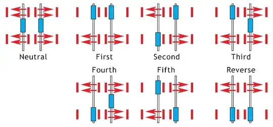
So here's what I want to build: a small bracket that will fit nicely under my shift boot and relay enough information to the Arduino to determine the position of the shifter. This is different than some methods that try to infer the relationship by RPM and speed, as they cannot work when stopped or with the clutch in.

Ideally, I do not want anything touching the shifter. I could use two (or four) spring potentiometers, but they are $122/each or more! Plus I don't want any tension or touching of the shifter. I could use microswitches, but they may eventually get weak or be very sensitive to the bracket position, and would still touch the shifter.

Hall Effect

Hall Effect Sensor

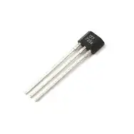
What I'd like to use is either Hall Effect Sensors or Proximity Sensors. Hall Effects are cheap (~$0.25 on eBay), and I'd prefer to use them. Would they be sensitive enough to pick up the shifter moving close to them? Would they continue to sense the presence, or do they only sense movement? Would I have to magnetize the shifter? Do I want Latching ones? Could someone explain how to use these in a manner that the Arduino can sense, and/or provide a diagram for this?

Proximity Sensors

Proximity Sensor

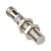
The other option would be Proximity sensors, which look to be about $22/each at the cheapest, so buying six would be pricey and not fit well under the shift boot. Would these work without magnetizing the shifter?

Are there other options?

Edit

I'm now between using microswitches and the cheap hall effect sensors pictured above. Could someone familiar with HE sensors draw me up a simple wiring diagram for how best to wire one to an arduino? They say they'll sense 5-8mm in distance, so this should be enough as I'll be mounting them near the base of the shifter shaft. Also, what magnet(s) should I use on the shifter? And help on how many / what strength I'll need?

Ehryk
  • 1,141
  • 5
  • 16
  • 28
  • Count speedometer pulses and engine RPM pulses. Gears are very fixed ratio. – Bryan Boettcher Jan 07 '13 at 22:08
  • 1
    Hall effect looks like a win from price standpoint. Yes you need magnets on the shifter. No you don't need latching. They work by position, not movement. – gbarry Jan 07 '13 at 22:10
  • @insta, that only works if the clutch is closed (i.e. vehicle is in motion), and will likely be unstable at low vehicle speeds. – HikeOnPast Jan 07 '13 at 22:11
  • 1
    BTW, I was taught to drive a manual transmission...by my girlfriend! – gbarry Jan 07 '13 at 22:13
  • Correct, @HikeOnPast. I'm not interested in speedo/RPM pulses because I want this to display what gear is engaged even at a stop - clearly that method is incapable of delivering this, and while the clutch is in it would read erroneous gears. – Ehryk Jan 07 '13 at 22:33
  • looks like epoxy, rare earth magnets and those cheap sensors will be the basic kit you need. Add that into your question and I'm sure someone will run with it. – placeholder Jan 07 '13 at 22:48
  • The new VW Golf 6 has that function built in from the factory as a method of showing you the "correct" gear for fuel economy. I highly suspect they just check the engine speed and road speed and calculate which gear you are actually in, with no sensor on the gear stick. If you are better at MCU programming and wireing cables, your OBDII port is your friend. – winny Jul 05 '17 at 14:05

3 Answers3

3

This is actually harder than it looks to get repeatable.

I would not recommend hall effect sensors for this application. Their sense distances are generally small, meaning that the mounting of the sensors and magnet need to be done with some precision. You will find it very challenging to align all of the halls to work consistently and under all operating conditions.

The transmission will move on its compliant mounts as a function of engine torque. If you're dealing with a top-loader transmission, the shift lever will also move relative to the body as a function of engine torque, making it almost impossible to obtain repeatable measurements.

Edit: The OP has a top-loader style transmission, where there is no external linkage to take advantage of. For any other transmission, there is external linkage between the shifter and transmission housing - usually rods or cables.

For a top loader: I'd recommend X and Y axis potentiometers on the shifter, with the pots mounted to the transmission (not the body), which should be accessible through the floorpan opening that the shifter comes up through. You'll need to decode the analog readings from the two pots to match gear selection.

For any other transmission: I'd recommend using a sealed potentiometer used as a voltage divider connected to each shift linkage (under the body, not inside the transmission). You'd then do the calibration + windowing in your firmware, where it will be easier to tune. If your transmission has multiple linkages, it essentially de-muxes some of the multidimensionality out of the shifter for you, again making it easier to map discrete gears to analog voltage ranges.

Reverse is easy--just tap the back up light circuit.

HikeOnPast
  • 7,306
  • 2
  • 25
  • 20
  • I'm not sure if it's a Top Loader or not, it's a 2003 Jeep Wrangler Rubicon 5spd. (do you mean http://en.wikipedia.org/wiki/Ford_Toploader_transmission ?) I'd also rather not magnetize my shifter (or stick a magnet on it), so what's left? I'm leaning toward micro switches. – Ehryk Jan 07 '13 at 23:23
  • You mention connecting pots to the linkages, I'm not sure if you mean actually getting access into the transmission or not. I really just want this tucked under the shift boot, as unobtrusively as possible – Ehryk Jan 07 '13 at 23:24
  • 1
    I would not recommend opening the transmission -- many manual transmissions have external linkages to connect the shifter to the transmission. I believe you have a top loader transmission (i.e. the shifter linkage is all internal to the transmission). I'm sorry to say that your task just got even harder. You could try X-Y pots on the shifter and see if you can enforce enough deadband in your software to reject movement caused by engine torque. – HikeOnPast Jan 07 '13 at 23:28
2

Edit: Well, if HikeOnPast is right, this won't work for you either (as you have no shifter linkages to deal with mechanically)... The best bet for this to work for you would be to create some sort of mask that sits on top of the shifter unit under the boot with 6 optosensors, and then attach a mask to the shifter to obstruct the sensors as necessary to determine which position it's in. The mechanical design would be a huge PITA, though. I'm not deleting this answer though, since I think this is a decent solution to someone else who might want to do the same in a different car (like me! I've been thinking about something like this for a while).


Another idea would be to use optosensors/magnetic sensors along the shifter cables (assuming your car uses shifter cables, and not some other sort of system, like hydraulics). I think optosensors would be cheaper. You'd need 2-4 of them, two for each cable. You put the optosensor around each cable (one end on one side of the cable, one end on the other side), then attach some sort of mask to the cable that will block the sensor when the shifter is in a certain position. Attaching the mask to the cable wouldn't affect the shifter travel/tension at all, and would be a lot more repeatable than using sensors directly on the shifter itself. The biggest problems I would foresee would be the availability of space around the shifter cables under the dash (before they cross into the firewall), and the fact that you'll have to take apart a good amount of your dash to get a good amount of room to work with.

Sensors

In this diagram, it's assumed you have a 5spd car that uses two linkages. The simplest way would be to use 4 optosensors to act as digital I/O for the uC. The red bars/arrows signify the optosensors, the blue bars the mask attached directly to the moving part of the linkage, and the black rectangle the linkage itself. Extrapolating the position of the shifter is real simple with this. If both left sensors on the left cable are unblocked, you know that the transmission is in neutral (regardless of the right cable). Otherwise, the transmission is in gear, and which gear is determined by the sensors that are blocked.

Shamtam
  • 3,546
  • 19
  • 27
  • I don't have a shifter cable. This is a 4WD Jeep with a longitudinally mounted transmission, and the shifter drops straight into the transmission housing like this: http://www.novak-adapt.com/knowledge/nv3550.htm – Ehryk Jan 08 '13 at 00:00
2

Mounting something to the shifter itself, hidden under the boot, is probably the best way to go.

A two-dimensional linear encoder strip, perhaps made of plastic, could be made as a collar that is mounted around the shifter and attached to it. The collar is white, with black patterns printed on it. Or perhaps transparent. You might be able to get away with a laser-printed transparency.

These patterns are scanned by optical sensors. The arrangement is such that if the stick is moved back and forth, only the back-and-forth sensors are driven with a quadrature signal which can be decoded to give the direction of movement and position. The side-to-side sensors do not see a change in the pattern because it is wide compared to conventional linear encoders. And vice versa. The picture gives a hint at the basic idea.

Basic Idea

Kaz
  • 19,838
  • 1
  • 39
  • 82
  • Can an Arduino do optical scanning? How would that work? How much do they cost? I'm leaning heavily toward 6x $0.45 Hall Effect sensors and a magnet on the shift rod, unless convinced of something better/easier. – Ehryk Jan 08 '13 at 23:16