5

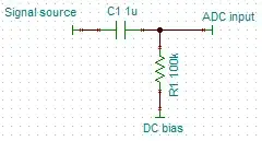
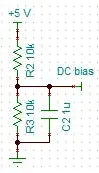
I was trying to use the ATMega328 ADC port A0 to read a signal. The hardware I used was:

The signal I got seems to be only the positive part of a sine wave. Is it possible that this setup isn't suited for audio recording? What I have to change?

Jader Dias
  • 1,963
  • 5
  • 23
  • 27

3 Answers3

3

Without having ever used any of those parts, let me see if I can take a stab. Do you happen to have access to an oscope? If so you might want to check your signal before you start building anything.

Most likely your microphone/amp is outputting a wave that is centered around 0v, meaning you have + and - voltages. Think of a sin wave that fluctuates between -1v and 1v. In order for your micro to use this, you will need to add a DC offset such that you most negative voltage becomes slightly above 0v and your most positive voltage is slightly below the max that your micro can read (probably around 5v).

With out looking into your components in more, it is hard to tell you specifically what you need to do in order to get your DC offset, but maybe this will put you in the right direction.

Kellenjb
  • 17,509
  • 5
  • 51
  • 87
3

Do you have a DC-blocking/biasing capacitor at the input?

Analog input with DC-blocking capacitor

The combination of the C with the R sets the lowest frequency that can pass through to the ADC. DC (the ultimate low frequency) is blocked, while AC passes through. In this case, the cutoff frequency would be 1 Hz, which is plenty low for audio.

The DC bias is provided by something in the middle of the ADC range, with low noise. For example:

DC bias source

This would produce 2.5 V at DC, but the AC is closely coupled to ground by the capacitor, so it filters out any fluctuations in the supply. A larger capacitor would improve the noise at lower frequencies.

(Originally I linked to this image, but that would only work if your 5 V supply is noise-free.)

endolith
  • 28,494
  • 23
  • 117
  • 181
  • Good schematic... I'll check it. – Jader Dias Oct 18 '10 at 01:41
  • What does this do, exactly? C1 must block the DC component of the signal, but why is that necessary? Does the R1/R2 pair then bias the signal such that 0v becomes 2.5? – blalor Oct 18 '10 at 01:48
  • 3
    @blalor strictly speaking 0V doesn't become 2.5V. The general rule is that the DC component of the signal becomes 2.5V – Jader Dias Oct 18 '10 at 01:54
  • 3
    @blalor if you were able to put an infinitely large capacitor in there, you would see that your entire signal is shifted to be centered around 0v. Hence, removing the DC offset. This is a common method to make sure that there isn't any circuit adding an unwanted offset. R1 and R2 then just add back a known dc offset for ADC purposes in this case. Since we can't have infinitely large caps we settle for smaller caps that cause some of the low frequencies to get cut off. – Kellenjb Oct 18 '10 at 02:22
  • 1
    Infinitely large caps would take forever to charge up to the bias voltage anyway. – endolith Oct 18 '10 at 13:48
  • @endolith eh, just those minor issues. – Kellenjb Oct 18 '10 at 15:02
  • @endolith I really like how you linked to wolframalpha, I think that is a great idea for showing people what the math was that went into it. – Kellenjb Oct 18 '10 at 15:05
  • I do that a lot. I love things like Google Calculator, Alpha, and Qalculate that can do freeform calculations with units and everything. – endolith Oct 18 '10 at 15:48
  • @endolith where is this schematic from? – Jader Dias Oct 18 '10 at 21:36
  • just a google image search, but now i can't find it. – endolith Oct 19 '10 at 00:09
  • 1
    @Jader: It was from here http://sites.google.com/site/ki4mcw/Home/arduino-tnc , but it's actually not a good circuit. I'll redraw it. – endolith Oct 19 '10 at 15:44
  • @endolith I mounted your circuit and it mantained the digital value of the DC component fixed as 688 (in a 10 bit scale). The ideal would be 512, but 688 is much better than what I had before (0). Then I realized that the mic alone won't be sufficient to change that. So I'm adding an Amp-Op to the circuit – Jader Dias Oct 20 '10 at 01:34
  • To get 512, change the upper resistor to something around 16.8K. :D The mic isn't changing the value at all? In that case, then yes, you'd need some gain from an op-amp. You still need to use this biasing circuit somewhere, though. – endolith Oct 20 '10 at 01:54
2

The solution is to use an Amp-Op

Pins

In a circuit like this:

Circuit

You can simulate it using the Java Circuit Simulator where you can import the following code:

$ 1 5.0E-6 10.20027730826997 57 5.0 50
g 240 240 240 288 0
r 240 112 240 160 0 47000.0
r 240 192 240 240 0 47000.0
R 240 112 240 80 0 0 40.0 5.0 0.0 0.0 0.5
r 272 384 336 384 0 1000.0
R 176 384 144 384 0 1 40.0 0.5 0.0 0.0 0.5
w 176 384 192 384 0
c 192 384 256 384 0 1.0000000000000001E-7 -2.9572014071857935
c 192 176 192 240 0 1.0000000000000001E-7 2.5000000000001608
w 192 240 240 240 0
w 256 384 272 384 0
w 336 384 336 192 0
r 416 240 512 240 0 100000.0
w 512 240 512 176 0
w 192 176 240 192 0
w 416 240 416 192 0
w 240 192 240 160 0
a 416 176 512 176 1 5.0 0.0 1000000.0
w 416 160 240 160 0
w 336 192 416 192 0
o 13 64 0 35 20.0 9.765625E-5 0 -1

The gain will be proportional to the ratio between the resistance of the 100k resistor and the 1k one.

Jader Dias
  • 1,963
  • 5
  • 23
  • 27