2

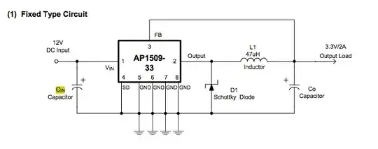
After finding out that a component I wanted to base a circuit around isn't suitable, I've found a possible replacement part, but I have questions about the values for Cin and Cout capacitors and the D1 diode.

The datasheet under the 'Fixed Circuit' diagram doesn't give me any hints as to the correct values for Cin, Co or D1. From other reading, it looks like a 1N4002FSTR-ND diode would do the job for D1. But how do I work out what I should be using for Cin or Co?

From what I understand, these are used to filter both input and output or stablise things, but I don't understand how you would select appropriate values for a circuit like this.

The circuit I'm trying to build can be seen below:

enter image description here

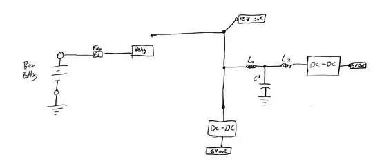
There is a single 12 V unfiltered output, a 5 V output with a filter (for audio devices but that provides for lower amp functions) and a 5 V unfiltered output for higher current uses (GPS and charging cell phone).

Sorry about the lack of inline images and the absence of an image for the DC-DC component, but as a new user, I'm not able to post images or more links than I have. I will add a comment with a link to the DC-DC component, taken from the datasheet.

The DC-DC component:

Trygve Laugstøl
  • 1,410
  • 2
  • 19
  • 28
  • http://i.imgur.com/yMv9k.png is the image for the DC-DC component of the circuit. – Anonymouslemming Jan 06 '13 at 15:55
  • It's better to use an automotive part (rather than 7805) in this application. Automotive power can be kinda rough. – markrages Jan 07 '13 at 17:50
  • I have no idea where I'd go to find an automotive part. The current solution in the bike seems to work well enough, and that's based on an MC3306 in a dodgy cigarette charger. – Anonymouslemming Jan 07 '13 at 18:22

2 Answers2

0

Diodes provides a lot more info for the part in this app note. It should be all you need to do the design.

Gustavo Litovsky
  • 7,619
  • 3
  • 25
  • 44
  • I was not aware of that App note - thanks a lot for the pointer! – Anonymouslemming Jan 07 '13 at 14:04
  • Could you explain what the app note means by the following: "If the designer selects a fixed output version of the AP1509, the resistor R1 shall be short and R2 shall be open." I was planning to buy the fixed 5v version. – Anonymouslemming Jan 07 '13 at 19:57
  • It means that R1 is 0 Ohm (basically just connect it, and then completely remove R2. Basically, you connect that pin of L1 to FB pin. There is no feedback (FB), so this pin might be called something else. – Gustavo Litovsky Jan 07 '13 at 20:02
  • Thanks. I'm starting to see why we leave this kind of work to professionals though. I'm struggling with the simple calculation for L(min) and haven't even got to the cap numbers yet :) – Anonymouslemming Jan 07 '13 at 20:10
  • Here is a post that talks about choosing buck inductors ( http://electronics.stackexchange.com/questions/49280/how-to-choose-a-inductor-for-a-buck-regulator-circuit/50597#50597 ). One method is fast, and gives an over estimate of inductance, while the other method discussed gives an optimal value. – gsills Jan 07 '13 at 21:15
  • Using the formula from the app note for inductance, I get a value of 51.563 μH for 2A at 5V (with a Vf of 0.5) for the inductor. For the output capacitor, I get an ESR value of 1.25 with a Vripple of 0.05V (1% of Vout at 5V). The input capacitor has the most math of the lot. For this, I get an RMS value of 1.1545 Do these sound right for this application? I will post my complete working out when I can scan it all tomorrow... – Anonymouslemming Jan 07 '13 at 22:32
0

It's considerably simpler to buy an off-the-shelf regulator that is designed to do what you want.

You have two choices in that area:

1) The venerable 7805 will give you a very nicely regulated 5V output of up to 1 amp. You will, however, need a heatsink to run that much power through it, and it will get hot. They are cheap and work very well with just a couple of components.

2) There are 7805 replacements that are switching power supplies where somebody else has done the design work for you. They are also quite simple to use, and because they are switching supplies, don't need a heatsink. I've used this one from Gravitech. They do, of course, cost more than the 7805 solution.

m.Alin
  • 10,638
  • 19
  • 62
  • 89
Eric Gunnerson
  • 1,216
  • 6
  • 6
  • Gravitech part link not showing up. – Anindo Ghosh Jan 07 '13 at 06:20
  • 1
    The original circuit (http://imgur.com/AelIO) used a 7805. But it put out too much heat to safely have that close to the fuel tank and I wasn't happy with the heatsink options under the seat. Hence the desire for a switching solution. I'd consider a switching replacement if I could find one for under GBP7 in a reasonable profile package and that can provide the amperage I require, but so far I've not been able to. – Anonymouslemming Jan 07 '13 at 17:24