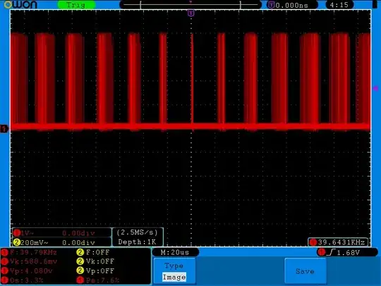
I have a project for automatic submersible pump actuation using a microcontroller.
I've done for two voltages like 5 V and 12 V and its corresponding relay. Also, in each board there is a transistor circuit for the motor actuation. It's nothing special. At any given time, the pump is getting actuated either by transistor circuit or by relay circuit, but not both at the same time.
Some points to be noted are:
- I'm driving the 5 V circuit using a 5 V, 5 A, DC adapter and the 12 V using a 12 V, 5 A, adapter.
- Motor current is around 250 mA. Is this circuit OK for the inrush current of the motor? I'd given the max value of i/p caps - is that OK?
- Is a reverse protection diode necessary at the power input side here? I'm powering the board using a DC jack and if I use a diode then there's a diode drop I've got to allow for in ADC calculations.
- I'm not using external reference voltage so I haven't connected the VREF.
- PCB snapshot is also attached. Let me know if you need any information from my side.
- Please check the overall circuit and let me know in case if I've to change something.
